Hi.I want to build quad405 assembled kit (my friend changed driver transistors and now it seems amps work ) with LLC smps. I will use metal enclosure.Should i isolate the T angle aluminium from the radiators? Radiator will be connected to the case of amp.
I was very excited about building quad 405 with llc smps but on YouTube I watched video that it does not measure good and he did not like the sound
Do you think it is worth to build ? I want to build an F5 turbo but my wife does not want such a big amp in living room and I want high power but slim amplifier with good sound maybe class aab. I have irs2092 amps but I want better sounding amp.
Quad and F5 are two entirely different beasts... built 405 (with Kevin Snook upgrades, and gotta say I love it... ofc it's personal preference, but I recommend it), if you looking for good versatile amp I would recommend P3A, well documented and many ppl built it.... SKA is also highly praised, or if you want something simpler one of LMXXXX iterations....
I liked LM3875/LM3886 sound a lot but i found bass was weak. I think i will build P3A but i have +-50v LLC SMPS.
Re: #5
Then first decide whether your power supply is more important than the amplifiers you plan to test. In any case, nominal 50V rail voltages can be used with some simple amplifiers if the power supply is carefully specified such that a conventional transformer and rectifier supply voltage droops somewhat and thus limits the available power under heavy loads. That and cost limiting, are good reasons for using small, E-I type transformers in commercial amplifiers.
Commercial SMPS usually deliver their nominal voltage with only a small range of adjustment. Also, their fixed current safety limit will likely be preset at slightly above their maximum rating but probably more than your amplifier can safely handle at that voltage. If you have the cheap type of SMPS intended for LED lighting, it will have standard fixed output voltages in increments of approximately 12V, like 24, 36, 48 etc. I have used +/- 36V SMPS for testing and permanent use in amps like P3a for many years now but beware that they may require a lot of careful EMI blocking measures at the power input, signal input and output plus interstage filtering too. Unfortunately, there is no straightforward, general procedure that doesn't depend on the whole design, including the PCBs, case, wiring, earthing, shielding and connected devices but I'm no expert at sorting out such problems either!
Many DIY and pre-assembled amp. module designs are ancient and have no EMI filtering at all, so you will need at least a good, wideband oscilloscope to find why the amp might sound rather poor when it should sound wonderful according to others with transformer power supplies. SMPS can still be fine though - if you are able to identify and remedy the likely new problems
Last edited:
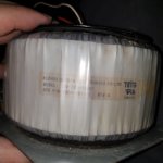
Nice collection!  but is your local AC supply suitable to power those "ADEL" metal cased trafos? I can read 100/110/115V (i.e. US domestic mains supply) power on a couple of them.
As you don't really need a high current power supply nor the specified maximum voltages to test your amplifier's sound quality in your home, it's possible that any of those transformers could be used for evaluation, assuming they are also suitable for connecting to your AC mains supply. You will, of course, need a transformer with 2 windings of the same secondary AC voltage or 2 similar transformers, each with a similar rating and connected in correct phase, to make a dual rail DC supply.
Many of the transformers are enclosed in a metal case and the shielding probably improves the noise level somewhat but If you do decide to use SMPS instead, don't forget to add grounded shielding around that power supply - nobody wants their audio signal sprayed with switching frequency harmonics whether the supply is alleged to be "soft switching" or not. No doubt, the noise will be reduced somewhat but "soft switching" SMPS in itself, seems like a contradiction in terms of efficient power transfer.
but is your local AC supply suitable to power those "ADEL" metal cased trafos? I can read 100/110/115V (i.e. US domestic mains supply) power on a couple of them.As you don't really need a high current power supply nor the specified maximum voltages to test your amplifier's sound quality in your home, it's possible that any of those transformers could be used for evaluation, assuming they are also suitable for connecting to your AC mains supply. You will, of course, need a transformer with 2 windings of the same secondary AC voltage or 2 similar transformers, each with a similar rating and connected in correct phase, to make a dual rail DC supply.
Many of the transformers are enclosed in a metal case and the shielding probably improves the noise level somewhat but If you do decide to use SMPS instead, don't forget to add grounded shielding around that power supply - nobody wants their audio signal sprayed with switching frequency harmonics whether the supply is alleged to be "soft switching" or not. No doubt, the noise will be reduced somewhat but "soft switching" SMPS in itself, seems like a contradiction in terms of efficient power transfer.
Last edited:
Hi. Transformers have 2 line of 0-100-115 maybe they can be used wiring in series to get 220ac input?
And I remembered i have another big toroidal approx 500w transformer in my other storehouse which was pulled from Logitech subwoofer as I remember it had 2 burned Elna capacitors and had about 5 chipamps as I remember they were tda7296. Maybe I can build 4 channel p3a with this big transformer.Will take picture of it asap.
And I remembered i have another big toroidal approx 500w transformer in my other storehouse which was pulled from Logitech subwoofer as I remember it had 2 burned Elna capacitors and had about 5 chipamps as I remember they were tda7296. Maybe I can build 4 channel p3a with this big transformer.Will take picture of it asap.
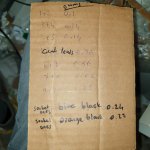
It's quite likely that you could use the 2 windings on the same transformer, in series, assuming they are similarly rated for current and not already connected internally - check first. When a conventional trafo is wound, it may be tapped at the ends of any winding layer but the windings must continue to be wound for the same number of turns in order to have a centre-tapped winding where the two halves have the same "sense" or winding direction, clockwise or anti-clockwise. If you connect separate windings in series but with reversed winding direction, they will cancel to zero output and you'll be shaking your head, confused.
So check out any markings, datasheet details etc. that may indicate the "sense" of the winding connections before cutting and wiring any leads. These days, winding sense is managed by fitting the coloured leads used according to schematics, the label on the box or published datasheets but it's also easy enough to wire them up and test for correct AC voltages before you make any connections to the diode bridge. In any case, its wise to know before you commit to layouts and lead lengths that could be hard to fix after mistakes are made.
BTW, a 500VA toroidal trafo is big enough to cause serious damage if you connect to something unwisely. Take extra care if you are experimenting and don't take risks.
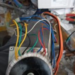
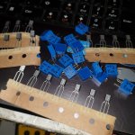
Hi. Here the transformer. It has many cables I do not know which ones are input and output.And I am collecting parts from storehouse I found bc546b bd140 and bd139 Philips and 2k trimmers fortunately.I think I will not pay money ( it became extremely expensive here our country)and make 4 channel amps but first I should identify cables of transformer
Attachments
Last edited:
There are ways of testing transformers to determine their windings and hence output voltages. However, this can be very dangerous and even lethal if you attempt to measure floating voltages or come in contact with a test voltage like the 230V mains AC. Best to begin with searching for leads coded by universal mains wiring colours like brown/red(A), blue(N) and green or the local equivalent of (E). Check that the winding shows the highest resistance between A and N leads, which usually identifies the mains leads of a small-medium size amp. but exposed leads and connectors must be safely insulated before you connect any fused and protected earth type of mains supply (via ELCB circuit breaker) and then check other windings using safety gloves at least, when powered. Mistakes not only can fry your transformer and non-mains cat.4 rated multimeter but can also kill or at least burn you in the process ⚰️.
Otherwise, I would not try to use any transformer that is not clearly identified as suitable for mains connection. I have found many toroidal transformers that were intended for industrial, isolated low voltage solar powered devices or portable equipment, even PA speakers that don't need high voltage insulation and any of these can and do fail when connected to mains supplies.
Otherwise, I would not try to use any transformer that is not clearly identified as suitable for mains connection. I have found many toroidal transformers that were intended for industrial, isolated low voltage solar powered devices or portable equipment, even PA speakers that don't need high voltage insulation and any of these can and do fail when connected to mains supplies.
The current limiter device is a 7.5A TVS resistor (a.k.a MOV or VDR) and rated at minimum 275V. It's also made by other manufacturers too, who use their own, different part numbers). Search any large distributor website for these by their part description/abbreviation online because manufacturers change products, locations, distributors etc. all the time.
- Home
- Amplifiers
- Solid State
- I want to build quad405 assembled kit.