Hi, can one of you kind persons help me understand what is going on here.
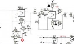
The image is from the IV and LP filters section of the Marantz CD65 DX standard tda1541A machine.
op amp IV stage 6585 (A): the 1k8 Resistor (3637) in he FB loop sets the voltage and 2n Cap (2645) over this restor helps keep things under control? Does this also form a LP filter?
Thre rest in the feedback loop of op amp 6585(A) is part of the deemph.
What is going on around 6585 (B)? I suspect its a second order LPF but I can't find a reference to the this lay out?
Why is inductor 1508 and capasitor 2647 in the feed back loop?
I assume this is forming a unity gain buffer with a LPF around it?
Thanks
Tom
Attachments
First stage
Vout = -Iin x Zfb...........so the transfer function is: -Vout/Iin = Zfb
The Zfb has a pole at around 42kHz, so it's a LPF combined with the I/V converter.
Second stage
This is a second order unity-gain Sallen–Key LPF (with that inductor added, you could sim it).
The L probably makes the cut-off sharper. The S-K filters use positive feedback around the unity gain block.
Last edited:
Thanks for the reply and transfer functions rayma,
I can see it now, seeing the +ve feed back loop tagged to the -ve feed back loop like it in this circuit confused me. I shall try and give it a sim just for fun.
Next question,
Where there are resistors in the signal path, would we get better results implimenting an inductor?
I can see it now, seeing the +ve feed back loop tagged to the -ve feed back loop like it in this circuit confused me. I shall try and give it a sim just for fun.
Next question,
Where there are resistors in the signal path, would we get better results implimenting an inductor?
In general no. However where there are RC filters in some cases if the R is replaced by L the filter has better performance.
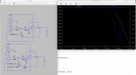
For thouse of you that are interested the bode pots are attached. Green is without the inductor.
Thanks abraxalito,
Better performance was what I should have said. I ammay be wrong but I was thinking along the lines of:
Less phisical restors in the signal path has got to be a good thing especially whe replaced with a wire.
I'm missing somemething with the inductor and the reactive resistance over the frequency range.
Time to play with spice and read up some more.
Attachments
Can't just replace R with L, the circuit has to be designed with the poles/zeros in the right places.
Inductors are usually less perfect than good (but still cheaper) resistors. Resistors are required to
control the filter Q. Ideal reactive elements (L and C) cannot dissipate power.
Inductors are usually less perfect than good (but still cheaper) resistors. Resistors are required to
control the filter Q. Ideal reactive elements (L and C) cannot dissipate power.
Last edited:
Inductors would have much more distortion than such circuitry could allow. They are the least linear passive component, except for air-core (which would have to be huge at audio frequencies at high impedances, much more so than low impedance crossover inductors). Synthesized inductors using gyrators are sometimes used, but they are linear....
Is the zero at 176.4 kHz?For thouse of you that are interested the bode pots are attached. Green is without the inductor.
- Home
- Source & Line
- Digital Source
- I/V to activetive filters.