Hi,
just a very vague idea and maybe nothing new:
How about connecting the DAC output to the output of an op amp ?
The op amp output provides virtual ground, it's + input is tied to ground.
Voltage swing is seen across resistors in the op amp rails.
Bernhard
just a very vague idea and maybe nothing new:
How about connecting the DAC output to the output of an op amp ?
The op amp output provides virtual ground, it's + input is tied to ground.
Voltage swing is seen across resistors in the op amp rails.
Bernhard
Bernhard said:Hi,
just a very vague idea and maybe nothing new:
How about connecting the DAC output to the output of an op amp ?
The op amp output provides virtual ground, it's + input is tied to ground.
Voltage swing is seen across resistors in the op amp rails.
Bernhard
I think that it will work...try it!!
Tell us about the sound quality 🙂
PS: The output is even balanced...i'm curius!...

Bernhard said:Just how to control offset ?
The opamp must have the feedback resistors...as usully...only nothing connected to the input...😉
Tube_Dude said:
The opamp must have the feedback resistors...as usully...only nothing connected to the input...😉
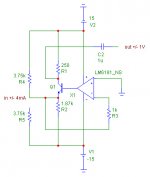
I meant the I/V output, not the input...
A quick & dirty schematic, the 3,75k used to simulate the 4mA current.
Again, maybe nothing new but as I am new to I/V, I don't know.
Can be built discrete too and without output cap...
Comments 😕
Attachments
Bernhard said:
I meant the I/V output, not the input...
A quick & dirty schematic, the 3,75k used to simulate the 4mA current.
Again, maybe nothing new and can be built discrete too and without output cap...
Comments 😕
I was thinking that that the current output of the dac was connected straight to the op amp output...
that way no offset to care...and the output will be in resistors in series with supply pins of the op amp...😉
Yes, I was thinking like this too, but then the signal is cut in positive and negative halfs and has to be put together again somehow.
On a sine current input there will be only a positive halfwave on the positive rail resistor.
And negative rail resistor respectively.
On a sine current input there will be only a positive halfwave on the positive rail resistor.
And negative rail resistor respectively.
Bernhard said:
On a sine current input there will be only a positive halfwave on the positive rail resistor.
And negative rail resistor respectively.
Not if you force the op amp to work in class A by a pull down resistor from the power rail ...😉
Bernhard said:Yes, I was thinking like this too, but then the signal is cut in positive and negative halfs and has to be put together again somehow.
On a sine current input there will be only a positive halfwave on the positive rail resistor.
And negative rail resistor respectively.
Biasing the op amp into class A with CCS at the o/p will give full o/p on one of the supply lines.
mike
just realised this will not be practical - tube dude's idea may be better
mikelm said:
Biasing the op amp into class A with CCS at the o/p will give full o/p on one of the supply lines.
mike
´
Yes...the CCS is even better than the resistor....and will inject much less suplly noise! 🙂
How is this done???Biasing the op amp into class A with CCS at the o/p will give full o/p on one of the supply lines.
ryssen said:
How is this done???
Actually the more I think about it the more I think I will stop thinking along these lines and focus more on the jocko/rudolf designs.
an example of how to bias op amps into class a is shown here.
http://www.diyaudio.com/forums/showthread.php?postid=327129#post327129
This approach to the above cct would mean that all of the current cycle would be drawn from one leg but when I was thinking on how to best convert this to a voltage I quickly came back to the jocko homo grounded base I- V i/p stage which makes the chip rather redundant.
that's my halfpenny worth
mike
Version with ccs. Works as does the one with transistor stage.
The output swings 5.5V to 9.5V.
What you all think ?
By the way if I put in NE5532 there are currents coming out of nowhere 🙁
Is it a bug in the spice model ?

The output swings 5.5V to 9.5V.
What you all think ?
By the way if I put in NE5532 there are currents coming out of nowhere 🙁
Is it a bug in the spice model ?
is that op amp stable without .1uF from the supply pins to earth ?
If not what do the caps to to the o/p frequency response ?
mike
If not what do the caps to to the o/p frequency response ?
mike
No idea, but one amp that I had built with output devices driven by op amp rails was stable even with fast cfb op amp.
Anyway the resistor can be mounted close to the op amp and so can be the decoupling cap.
Anyway the resistor can be mounted close to the op amp and so can be the decoupling cap.

- Status
- Not open for further replies.
- Home
- Source & Line
- Digital Source
- I/V conversion idea