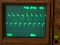
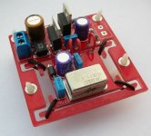
I purchased a clock kit from China at around US$15 + US$1.5 courier charge to Hong Kong that includes PCB, all components, a "so to say" 10 ppm oscillator and a 2VA transformer. After assembling, I measured the output voltage and it reads 2.5V but my oscilloscope reads overshooting. I am fighting if I should put it in my antique - Pioneer T-07A which has been in my service since 1990. Eventually, I used 3 hours to install it.
When started, it already sounds excellent - the low is having quicker response/punch, the mid is getting sweet and there are many more details that I never heard before. After running in for about 5 days, it even turns better.
My questions: -
1. What causes such overshoot?
2. Does the overshoot hurts?
3. How to kill the overshoot?
4. They have a so call 3 ppm oscillator that will cost me US$19 extra. Does it affect the sound quality in great extend by changing the 10 ppm oscillator to 3 ppm?
5. The circuit is very simple. Why there are so many clocks in the market that has a lot of components? How good are they?
Sunny
Attachments
My questions: -
1. What causes such overshoot?
2. Does the overshoot hurts?
3. How to kill the overshoot?
4. They have a so call 3 ppm oscillator that will cost me US$19 extra. Does it affect the sound quality in great extend by changing the 10 ppm oscillator to 3 ppm?
5. The circuit is very simple. Why there are so many clocks in the market that has a lot of components? How good are they?
-----------------------------------------------------------------------------------
You need to ensure that the clock output impedance is matched to the input impedance; try terminating into a 50R or 75R load.
You can kill some of the overshoot by mopunting a small capacitance across the output. Apparently some XOs like a bit of capacitance say 10 to 47 pf.
The clock looks quite well made. Can you give me details and I may order one myself.
Clock accurracy is not important. Low phase noise (jitter) is.
The suspension made me chuckle, so little mass so the resonant frequency is going to be quite high.
Sunsun22 said:
5. The circuit is very simple. Why there are so many clocks in the market that has a lot of components? How good are they?
Sunny
low noise psu >>> low phase noise sine wave oscillator >>> sine to square conversion
The extra parts go into the 1st and last bits.
Biggest problem will be layout so need a pcb!
I have yet to try feeding the sine wave directly into a decoder chip.
davidsrsb said:The suspension made me chuckle, so little mass so the resonant frequency is going to be quite high.
Hi.
Agreed but it shows that some thought has gone into the design.
It does look well made. If we had some conponent values and a shot of the underside, we could reverse engineer the circuit.
Andy
Works fine so long as it still meets the voltage swing expected by the input logic. Don't worry about the apparently 'slow' rise time, that matters less than the cycle-to cyclce variance a poorly-considered inverter will add(!).I have yet to try feeding the sine wave directly into a decoder chip.
Subjectively it worked quite well IME too - i.e. building a clock and coupling the sine output into a couple of cd players sounded better than using the original, and no discernable improvement came from then adding-in an inverter to square-up the signal. But then - that's also adding the inverter's sensitivity to PSU noise into the equation too...
Thank you for all the input. The measurement was made without loading. I will measure it when it is in operations. Yet, I still wonder should I install a more expensive clock in an attempt to even improve better?
At low currents like this a pi filter C-R-C on the rectifier and single stage of regulation may be better. R could be ~100R so the input to the reg will be nearly pure dc with just a small amount of 100Hz and low harmonics.
----------------------------------------------------------------------------------Sunsun22 said:Thank you for all the input. The measurement was made without loading. I will measure it when it is in operations. Yet, I still wonder should I install a more expensive clock in an attempt to even improve better?
It is not the cost, but the phase noise. No point in using a very low TC clock with poor jitter performance!
The url you posted does not exist diyhifi.net . Can you please repost.
If the circuit posted is the one you have, the clock signal is not coupled direct but relocked.
Sorry, it should be hifidiy.net
The circuit is the same for the kit that I bought. What is "relock"?
The circuit is the same for the kit that I bought. What is "relock"?
CLC filter
Right, CLC also works as in myclock, see also:
http://www3.sympatico.ca/add.automation/spice/ripple.htm
😎
davidsrsb said:At low currents like this a pi filter C-R-C on the rectifier and single stage of regulation may be better. R could be ~100R so the input to the reg will be nearly pure dc with just a small amount of 100Hz and low harmonics.
Right, CLC also works as in myclock, see also:
http://www3.sympatico.ca/add.automation/spice/ripple.htm
😎
????
Now is this shiny square thingie a crystal or a crystal-oscillator????
[ I guess it is a complete crystal-oscilator as it is powered from 5V supply. So information given is plainly wrong]
74VHC04 oscillator is not much better than standard in CDP.
How many times I have to xplain this ppm spec which is useless. It is NOT a jitter spec but a frequency deviation; can you hear this???
DO YOU HEAR ME CHINESE FRIENDS?
Here a direct link to that cheap clock:
http://en.hifidiy.net/shop/views.asp?hw_id=52
PCB suspension seems to be directly stolen from Madrigal Audio Systems. Shall I give them a hint? One or two LM317 NOT low enough noise IMHO, especially as Vadjust pin is not bypassed. See link in post # 15.
Re: CLC filter
Right, CLC also works as in myclock, see also:
http://www3.sympatico.ca/add.automation/spice/ripple.htm
😎 [/B][/QUOTE]
-----------------------------------------------------------------------------------
When the Jung regulator has been improved so much (ALW version), there is to me NO reason for going so far to canacel out noise, and with a highish output impedance too. I have obtained easilly<10 uV/1MHz with the Jung circuit.
Re: Re: CLC filter
Jung circuit not suitable for clock supply; been there done that.😎
You like to screw quoting systems fmak, jeeez!
-----------------------------------------------------------------------------------Right, CLC also works as in myclock, see also:
http://www3.sympatico.ca/add.automation/spice/ripple.htm
😎
fmak said:When the Jung regulator has been improved so much (ALW version), there is to me NO reason for going so far to canacel out noise, and with a highish output impedance too. I have obtained easilly<10 uV/1MHz with the Jung circuit.
Jung circuit not suitable for clock supply; been there done that.😎
You like to screw quoting systems fmak, jeeez!
1) There are clearly better voltage regulator circuits than that. It seems to be more complex than it has to be and uses OLD regulator technology versus new. Have to wonder why...
2) The 4 pin CAN is clearly an a self contained crystal Oscillator which means it has "very stable consistent TTL level output" if it's not overloaded.
3) The 74VHC04 is clearly just a wave shaper and buffer, nothing more. It is not the Oscillator portion of the circuit at all. It may even be contributing to the overshoot. Nothing in this design shows me that they are trying to control spurious hi frequency oscillations.
4) Since this is a self contained crystal oscillator package... Load capacitance on the crystal is irrelivent... it's somewhere inside the "can".
I'm still laughing about the "cradle".
To each his own I guess.
- Status
- Not open for further replies.
- Home
- Source & Line
- Digital Source
- I used a cheap cheap clock