Hello everyone,
I am a newbie with a project in mind, but I'm full of doubts and I need your expert opinion to see if it can work.
I have two 10" car subs (AUDIO SYSTEM - RADION 10 PLUS) and I found a plan of an old 10" back-loaded horn that I have slightly changed by reversing the cone and adding a closed rear chamber.
The result is the following:
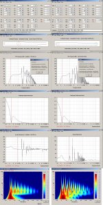
I tryed to model it with hornresp with the following results:
I also imported it in Akabak to simulate subsonic filter and low pass filter.
High pass 35Hz 24db - Low pass 85Hz 24db
The music I like is reggae roots and dub and I want to use it both outdoor and indoor.
I know it is ONLY a 10" so I don't expect to destroy buildings with two of these horns.
Just some good bass (at least louder than a 60L with Fb 35Hz).
My first and greatest doubt is about group delay peaks at 40Hz and ~100Hz. Mainly the ~100Hz one!
The only horn I've heard is PD1850 SUPER SCOOPER which for my ears is fast enough when playing dub music.
I know that 10" is not 18" but what I want to understand is if group delay is so bad.
I found this simulation with hornresp and you can see that group delay is quite similar (PD1850 black - RADION10PLUS grey).
I can also add a delay of ~8/10ms on the mid-highs so that group delay between 60-80Hz can be considered as near 0ms.
Second doubt is about cone displacement.
If xmax is 8mm can I consider 10-12mm to be the xmech?
What happens in sealed rear chamber with displacement greater than xmax? Will the sub get too "hot"?
Is a rear vented chamber tuned to about 30Hz a good idea?
Even lower to take port group delay peak not over the 40Hz existing group delay.
Third doubt is about the wood thickness and foldings.
Is 16mm chipboard acceptable without bracing? Internal cab width is 40cm.
Are there too many folds in your opinion? Will they change the response too much?
I'd be really grateful if you help me with your answers and your comments.
If I said too much rubbish please correct me as much as you can.
Thanks in advance.
PS. Here is a cad rendering to let me dream 🙂
I am a newbie with a project in mind, but I'm full of doubts and I need your expert opinion to see if it can work.
I have two 10" car subs (AUDIO SYSTEM - RADION 10 PLUS) and I found a plan of an old 10" back-loaded horn that I have slightly changed by reversing the cone and adding a closed rear chamber.
The result is the following:
An externally hosted image should be here but it was not working when we last tested it.
I tryed to model it with hornresp with the following results:
An externally hosted image should be here but it was not working when we last tested it.
An externally hosted image should be here but it was not working when we last tested it.
An externally hosted image should be here but it was not working when we last tested it.
An externally hosted image should be here but it was not working when we last tested it.
An externally hosted image should be here but it was not working when we last tested it.
An externally hosted image should be here but it was not working when we last tested it.
I also imported it in Akabak to simulate subsonic filter and low pass filter.
High pass 35Hz 24db - Low pass 85Hz 24db
An externally hosted image should be here but it was not working when we last tested it.
The music I like is reggae roots and dub and I want to use it both outdoor and indoor.
I know it is ONLY a 10" so I don't expect to destroy buildings with two of these horns.
Just some good bass (at least louder than a 60L with Fb 35Hz).
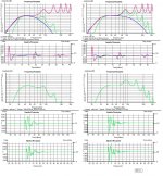
My first and greatest doubt is about group delay peaks at 40Hz and ~100Hz. Mainly the ~100Hz one!
The only horn I've heard is PD1850 SUPER SCOOPER which for my ears is fast enough when playing dub music.
I know that 10" is not 18" but what I want to understand is if group delay is so bad.
I found this simulation with hornresp and you can see that group delay is quite similar (PD1850 black - RADION10PLUS grey).
An externally hosted image should be here but it was not working when we last tested it.
I can also add a delay of ~8/10ms on the mid-highs so that group delay between 60-80Hz can be considered as near 0ms.
Second doubt is about cone displacement.
If xmax is 8mm can I consider 10-12mm to be the xmech?
What happens in sealed rear chamber with displacement greater than xmax? Will the sub get too "hot"?
Is a rear vented chamber tuned to about 30Hz a good idea?
Even lower to take port group delay peak not over the 40Hz existing group delay.
Third doubt is about the wood thickness and foldings.
Is 16mm chipboard acceptable without bracing? Internal cab width is 40cm.
Are there too many folds in your opinion? Will they change the response too much?
I'd be really grateful if you help me with your answers and your comments.
If I said too much rubbish please correct me as much as you can.
Thanks in advance.
PS. Here is a cad rendering to let me dream 🙂
An externally hosted image should be here but it was not working when we last tested it.
Very interesting project, although I don´t like horns, I prefer the classic Karlson Speaker Project. I have 3 of them and plays pretty fine.
Good luck in your buildings.
Good luck in your buildings.
Can you link some 10 inch plans for that design?
Is it good for a subwoofer playing from 40Hz to 90/100Hz?
Thank you
Is it good for a subwoofer playing from 40Hz to 90/100Hz?
Thank you
Wow!! Something to study!
Thx Bjorno.I also noticed that your parameters are different and I re-typed them in hornresp.
You are right.
The front loaded horn is the one I'm interested in.
79,55Hz red line in group delay graph is there to confirm that I can't use it till 90/100Hz, am I right? Anyway I will try to make a box out of it in autocad.
IMHO the other designs you posted have similar performance to a reflex 60L 28Hz.
Is there something particular that I have not undestood??
PS. If the horn will be a success I will call it the RABJHORN 🙂
[drbis84:..I also noticed that your parameters are different and I re-typed them in hornresp..
Hi, I guess the best way is to actually measure the driver. but for this case I just let HR to calculate BL value consistent with the other published numbers.
79,55Hz red line in group delay graph is there to confirm that I can't use it till 90/100Hz, am I right? Anyway I will try to make a box out of it in autocad.
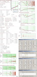
The 80 Hz mark just confirms an IMO optimal XO point as the gldy is lower than my design max= ~9.4 mS but if you want to XO higher up( I guess 145 Hz would be OK(24dB LR LPF)) you must place damping material (loose a dB or two) near the throat or multi fold the enclosure to lower the gldy enough to be blameless.
IMHO the other designs you posted have similar performance to a reflex 60L 28Hz.
Is there something particular that I have not undestood??
I don't know they are only submitted as other possible examples of sub's using your driver.
PS. If the horn will be a success I will call it the RABJHORN 🙂

b🙂
The 80 Hz mark just confirms an IMO optimal XO point as the gldy is lower than my design max= ~9.4 mS but if you want to XO higher up( I guess 145 Hz would be OK(24dB LR LPF)) you must place damping material (loose a dB or two) near the throat or multi fold the enclosure to lower the gldy enough to be blameless.
Hi Bjorno,
thanks for your detailed reply.
I would like to use it with your suggested 80Hz 24dB LR LPF and this would take to a roll-off after 100Hz but at 93Hz the group delay peaks and this is a problem with kick drums, isn't it?
An externally hosted image should be here but it was not working when we last tested it.
Can you give me an explanation on how multi foldings affect group delay?
I thougth that folding a horn was just a compromise to reduce overall dimensions but at some expense. It is the first time I read that such compromise introduces some advantages (in particular in terms of group delay).
This thing is really really interesting!!
I found in akabak manual this method to simulate a 90° bend in a vent.
An externally hosted image should be here but it was not working when we last tested it.
Do you think that I can apply this method on the project script to see how group delay changes? Or such change would not be simulated?
I also want to inform you that the main source of my sound system will be a pc with a semi-pro sound card.
So if you know a dsp software that can modify group delay or a particular digital crossover for a better result it would be a good solution.
Thanks again for your suggestions!
Hi Bjorno,..thanks for your detailed reply..I would like to use it with your suggested 80Hz 24dB LR LPF and this would take to a roll-off after 100Hz but at 93Hz the group delay peaks and this is a problem with kick drums, isn't it?
An externally hosted image should be here but it was not working when we last tested it.
Yes this peak could play XO havoc when integrating with the mains but it looks much worser than the reality would show.See the HOLMimpulse simulations where the 145 Hz filter ( no stuffing in use) in use cannot suppress the peaks enough but if you fold and slightly stuff at correct position could be nearly complete eliminated.
Can you give me an explanation on how multi foldings affect group delay?..I thougth that folding a horn was just a compromise to reduce overall dimensions but at some expense. It is the first time I read that such compromise introduces some advantages (in particular in terms of group delay)...This thing is really really interesting!!..I found in akabak manual this method to simulate a 90° bend in a vent.
An externally hosted image should be here but it was not working when we last tested it.
Yes foldings will act like FR/distance inserted HPF:s and with the AKAbak you can insert the acoustic mass element between the straight ducts that in reality always have a flow resistance in series much depending if (on) damping materials inserted.
Do you think that I can apply this method on the project script to see how group delay changes? Or such change would not be simulated?
Yes if you simulate your FLH with the corner elements you should see improvements.I prefer to use MJK:s program as it's easier to chose where to insert damping materials..the amount needed and the density too.
Have a look at the submitted MJK FLH sim.
b 🙂
Attachments
Hi bjorno, thanks for the explanations and for the detailed simulations.. I'm developing the design in cad.. I found it is quite simple if i design a spiral geometry in order to have only 90 degrees folding and with the plan in hands i will try to make simlations in akabak with bends assuming that stuffing will reduce the higher peak further more.. I will keep you informed.. 🙂
Hi Bjorno,
here is a first prototype.
It is as tall as the actual bass reflex and twice deep.
The only problem is that it is 10cm shorter because I started folding from the mouth back to the throat and it did not fitted all 300cm.
Rear chamber will be tunable from 10 to 28 liters.
I'm going to simulate Akabak response with a acoumass
Just a doubt on bends and waveguides, if you know what to do:
90° bend simulation in my posted image seems to refer only to ducts having costant heigth so i don't know which heigth i should consider having a waveguide (at the throat of the bend,at the mouth of the bend or an average value?)
And in addition it seems from the image that Akabak considers only the length of straight parts even if the bend is part of the path.
If you use akabak F1-HELP under ACOUMASS-EXAMPLES section it considers instead a tube of 50cm with a bend beginning after 20cm as [20cm+acoumass+30cm] so the sum of the duct is still 50cm.
Which method should I use?
First one seems to simulate a shorter path and response falls in the lower end.
I will try the second.
In any case I've noticed the positive effect on group delay! 😀
PS. I have seen a video of giant green horns in finland and read about one of the designers called Bjorn. Is it you?!?!?!?😱😱😱😱
here is a first prototype.
An externally hosted image should be here but it was not working when we last tested it.
It is as tall as the actual bass reflex and twice deep.
The only problem is that it is 10cm shorter because I started folding from the mouth back to the throat and it did not fitted all 300cm.
Rear chamber will be tunable from 10 to 28 liters.
I'm going to simulate Akabak response with a acoumass
Just a doubt on bends and waveguides, if you know what to do:
90° bend simulation in my posted image seems to refer only to ducts having costant heigth so i don't know which heigth i should consider having a waveguide (at the throat of the bend,at the mouth of the bend or an average value?)
And in addition it seems from the image that Akabak considers only the length of straight parts even if the bend is part of the path.
If you use akabak F1-HELP under ACOUMASS-EXAMPLES section it considers instead a tube of 50cm with a bend beginning after 20cm as [20cm+acoumass+30cm] so the sum of the duct is still 50cm.
Which method should I use?
First one seems to simulate a shorter path and response falls in the lower end.
I will try the second.
In any case I've noticed the positive effect on group delay! 😀
PS. I have seen a video of giant green horns in finland and read about one of the designers called Bjorn. Is it you?!?!?!?😱😱😱😱
Hi drbis84,
Here are two threads that I think may help:
Horn Folding in Sketch-Up - AVS Forum , and
http://www.diyaudio.com/forums/subwoofers/175658-tham15-compact-15-tapped-horn-21.html , particularly Post #202.
Regards,
Here are two threads that I think may help:
Horn Folding in Sketch-Up - AVS Forum , and
http://www.diyaudio.com/forums/subwoofers/175658-tham15-compact-15-tapped-horn-21.html , particularly Post #202.
Regards,
Hi tb46, thank you very much for the links!! I will check them!!
I want also to clarify another point:
In bjorno's suggested design compression ratio is 3 against tutorials suggested 2.. Could this high ratio in combination with rear closed chamber put to much stress on paper cone or on the coil generating for example high temperature?? Can you describe in general the behaviour of the driver with respect to compression ratio?? Thx in advance!!
Hi drbis84,
You have to know the driver-and the usage-to know how much compression would be too much (and I don't). Another thread:
http://www.diyaudio.com/forums/subw...-compression-ratio-different-perspective.html
Regards,
You have to know the driver-and the usage-to know how much compression would be too much (and I don't). Another thread:
http://www.diyaudio.com/forums/subw...-compression-ratio-different-perspective.html
Regards,
Hi tb46,
I read the links about bends and I want to use wood curves as shown in the last image and smooth the 90° internal angles to keep the horn the most constant possible (according to my ability with construction of course ) and such problems should be minimized, am I right?
Regarding folding method I used the same method with autocad.
I will try to fold it in another way to use all 3 meters.
Link about compression and air velocity didn't clarify my doubt but I'm confident that I will find something about this on web.
Thank you very much for your links
A lot of informations anyone interested in horns building should read.
🙂
I tried to simulate bends considering all the length as suggested in AKABAK F1 HELP MENU.
The result with total length of 290cm and acoumass elements for the bends is the following:
Def_Const
{
S1 = 115.00e-4; |Horn segment 1 throat area (sq cm)
S2 = 135.00e-4; |Horn segment 1 mouth area and horn segment 2 throat area (sq cm)
S3 = 600.00e-4; |Horn segment 2 mouth area (sq cm)
L12 = 13.00e-2; |Horn segment 1 axial length (cm)
L23 = 277.00e-2; |Horn segment 2 axial length (cm)
Vrc = 20.00e-3; |Rear chamber volume (litres)
Lrc = 20.00e-2; |Rear chamber average length (cm)
Vtc = 622.90e-6; |Throat chamber volume (cc)
Atc = 346.50e-4; |Throat chamber cross-sectional area (sq cm)
Sd = 346.50e-4;
Arc = Vrc / Lrc;
Ltc = Vtc / Atc;
}
Def_Driver 'Driver'
Sd=346.50cm2
Bl=13.52Tm
Cms=3.50E-04m/N
Rms=3.46Ns/m
fs=28.0004Hz |Mmd = 88.59g not recognised by AkAbak, fs calculated and used instead
Le=1.00mH
Re=3.60ohm
ExpoLe=1
|Filter 'HIGHPASS' fo=25Hz vo=1
| {b4=1; a4=1; a3=2.828427; a2=4; a1=2.828427; a0=1; }
|
|Filter 'LOWPASS' fo=90Hz vo=1
| {b0=1; a4=1; a3=2.828427; a2=4; a1=2.828427; a0=1; }
System 'System'
Driver Def='Driver''Driver'
Node=1=0=5=6
Duct 'Rear chamber'
Node=4=5
SD={Arc}
Len={Lrc}
Visc=0
Duct 'Throat chamber'
Node=6=9
SD={Atc}
Len={Ltc}
Visc=0
Waveguide 'Horn segment 1'
Node=8=9
STh=113.4cm2
SMo=141.6cm2
Len=13.7cm
Conical
Waveguide 'Horn segment 2'
Node=9=10
STh=141.6cm2
SMo=179.1cm2
Len=11.7cm
Conical
AcouMass 'Ma1' Node=10=11 Ma={ 1.85/0.0597 }
Waveguide 'Horn segment 3'
Node=11=12
STh=179.1cm2
SMo=244.8cm2
Len=50cm
Conical
AcouMass 'Ma1' Node=12=13 Ma={ 1.85/0.0816 }
Waveguide 'Horn segment 4'
Node=13=14
STh=244.8cm2
SMo=308.4cm2
Len=32.7cm
Conical
AcouMass 'Ma1' Node=14=15 Ma={ 1.85/0.1028 }
Waveguide 'Horn segment 5'
Node=15=16
STh=308.4cm2
SMo=400.5cm2
Len=60cm
Conical
AcouMass 'Ma1' Node=16=17 Ma={ 1.85/0.1335 }
Waveguide 'Horn segment 6'
Node=17=18
STh=400.5cm2
SMo=478.5cm2
Len=47,25cm
Conical
AcouMass 'Ma1' Node=18=19 Ma={ 1.85/0.1595 }
Waveguide 'Horn segment 7'
Node=19=20
STh=478.5cm2
SMo=600cm2
Len=74,71cm
Conical
Radiator 'Horn mouth'
Node=20
SD=600cm2
I don't understand if it is correct and if it better than before..
Any opinion?
The result with total length of 290cm and acoumass elements for the bends is the following:
Def_Const
{
S1 = 115.00e-4; |Horn segment 1 throat area (sq cm)
S2 = 135.00e-4; |Horn segment 1 mouth area and horn segment 2 throat area (sq cm)
S3 = 600.00e-4; |Horn segment 2 mouth area (sq cm)
L12 = 13.00e-2; |Horn segment 1 axial length (cm)
L23 = 277.00e-2; |Horn segment 2 axial length (cm)
Vrc = 20.00e-3; |Rear chamber volume (litres)
Lrc = 20.00e-2; |Rear chamber average length (cm)
Vtc = 622.90e-6; |Throat chamber volume (cc)
Atc = 346.50e-4; |Throat chamber cross-sectional area (sq cm)
Sd = 346.50e-4;
Arc = Vrc / Lrc;
Ltc = Vtc / Atc;
}
Def_Driver 'Driver'
Sd=346.50cm2
Bl=13.52Tm
Cms=3.50E-04m/N
Rms=3.46Ns/m
fs=28.0004Hz |Mmd = 88.59g not recognised by AkAbak, fs calculated and used instead
Le=1.00mH
Re=3.60ohm
ExpoLe=1
|Filter 'HIGHPASS' fo=25Hz vo=1
| {b4=1; a4=1; a3=2.828427; a2=4; a1=2.828427; a0=1; }
|
|Filter 'LOWPASS' fo=90Hz vo=1
| {b0=1; a4=1; a3=2.828427; a2=4; a1=2.828427; a0=1; }
System 'System'
Driver Def='Driver''Driver'
Node=1=0=5=6
Duct 'Rear chamber'
Node=4=5
SD={Arc}
Len={Lrc}
Visc=0
Duct 'Throat chamber'
Node=6=9
SD={Atc}
Len={Ltc}
Visc=0
Waveguide 'Horn segment 1'
Node=8=9
STh=113.4cm2
SMo=141.6cm2
Len=13.7cm
Conical
Waveguide 'Horn segment 2'
Node=9=10
STh=141.6cm2
SMo=179.1cm2
Len=11.7cm
Conical
AcouMass 'Ma1' Node=10=11 Ma={ 1.85/0.0597 }
Waveguide 'Horn segment 3'
Node=11=12
STh=179.1cm2
SMo=244.8cm2
Len=50cm
Conical
AcouMass 'Ma1' Node=12=13 Ma={ 1.85/0.0816 }
Waveguide 'Horn segment 4'
Node=13=14
STh=244.8cm2
SMo=308.4cm2
Len=32.7cm
Conical
AcouMass 'Ma1' Node=14=15 Ma={ 1.85/0.1028 }
Waveguide 'Horn segment 5'
Node=15=16
STh=308.4cm2
SMo=400.5cm2
Len=60cm
Conical
AcouMass 'Ma1' Node=16=17 Ma={ 1.85/0.1335 }
Waveguide 'Horn segment 6'
Node=17=18
STh=400.5cm2
SMo=478.5cm2
Len=47,25cm
Conical
AcouMass 'Ma1' Node=18=19 Ma={ 1.85/0.1595 }
Waveguide 'Horn segment 7'
Node=19=20
STh=478.5cm2
SMo=600cm2
Len=74,71cm
Conical
Radiator 'Horn mouth'
Node=20
SD=600cm2
An externally hosted image should be here but it was not working when we last tested it.
I don't understand if it is correct and if it better than before..
Any opinion?
Hi Bjorno,
in the post above I simulated the bends and IMO the result is not so exciting.
What do you think about this change in the response? Is it expected?
Should I design a straigth horn with a higher response in the lower region and expect that this response will be flat after the insertion of acoumass bends??
A picture just to describe what I'm thinking about:
An externally hosted image should be here but it was not working when we last tested it.
Hi Bjorno,
in the post above I simulated the bends and IMO the result is not so exciting.
What do you think about this change in the response? Is it expected?
Should I design a straigth horn with a higher response in the lower region and expect that this response will be flat after the insertion of acoumass bends??
A picture just to describe what I'm thinking about:
An externally hosted image should be here but it was not working when we last tested it.
Hi, Its not correct to use the physical full length of the enclosure + the sum of distributed mass-element bends.
All your ducts should be shorter and the 'bends' physical lengths should not be added.
Reason is: From bend input boundary to output only the area change is interesting and the physical length is already included i the acoustic mass.
b 🙂
PS:Submitting a picture that might help you for deeper understanding:
Attachments
- Status
- Not open for further replies.
- Home
- Loudspeakers
- Subwoofers
- I NEED YOUR HELP!! 10" Front loaded sub design THE RADIHORN