Hi,
did the bulb flash briefly and go out?
The flash is the start up current in the transformer and as it goes out, that is the smoothing caps charging up.
When the bulb is off, the amp should be drawing only quiescent current.
The rail fuses should have been replaced with 10r resistors to allow you to measure the quiescent current.
Then check that the output bias current is just a little bit low or much less.
Check the output offset and then when everything measures well remove the light bulb. Repeat all the checks and adjustments and finally add a dummy load.
i didnt know about the 10r on the rails, ill make sure that i use them on this next coming amp.
i had ran a signal from my comp sound card to the amp, was watching the input and output signals on my scope, there was some distortion on the output signal, i was adjusting the bias pot when it went out.
but i think that the two wires coming from the bulb to the trafo touched each other thus bypassing the bulb and allowing full current to go the amp, since they where so close, i couldn't find anything else that could of gone wrong.
but then again im no electronics engineer.
ill follow those instruction on the next amp, anything else i should know so that the next amp don't end up like this one.
any online articles you guys recommend, i search but dint find anything relevant.
later
leave the output with just the stabilising network.
Short the input.
Then power up through the bulb.
Measure the voltages around the amp and confirm they are close to design values.
measure output offset.
Measure output noise.
Measure output bias.
Then remove bulb from mains supply and repeat all those checks and measurements.
Now check the ripple on the PSU using the scope. check the output of the amp on the scope.
Set up the output bias still with the 10r instead of rail fuses.
Switch off, reconnect the bulb and connect a dummy load and recheck everything.
Disconnect the bulb and recheck.
When it's passed all those and you have about 30minutes running time with no components showing any signs of overheating, then think about applying a signal to the input.
Somewhere about now you can replace the rail fuses.
Thats exactly the kind of info i was looking for.
Thanks a bunch.
im making the new pcb as i type this.
i should be done in a couple of hours, so ill be testing tomorrow most likely,
thanks again ill let you all know how it goes.
laters
Thanks a bunch.
im making the new pcb as i type this.
i should be done in a couple of hours, so ill be testing tomorrow most likely,
thanks again ill let you all know how it goes.
laters
Hi Adrew T,
I'm impressed about your knoweledge on amps. It seems like you've been doing this for a while. I'm not trying to change the topic here but since you mentioned about the things need to be check/adjusted on the amp, can you recommend a book using oscilloscope on testing amps? Thanks.
I'm impressed about your knoweledge on amps. It seems like you've been doing this for a while. I'm not trying to change the topic here but since you mentioned about the things need to be check/adjusted on the amp, can you recommend a book using oscilloscope on testing amps? Thanks.
Update, it finaly works!!!!
hello everybody. i finally got the amplifier to work. some how my oscilloscope which was hooked to the speakers was causing oscillation which was killing the amp. i went trough 5 chips before noticing that was the problem. fool me. lol.
the amp sounds great though. the square wave has some sharp tips on both ends but is very square, the sine wave is perfect.
one problem i have is that when i try to adjust the bias it doesn't seem to make any changes on how the output wave looks, it does changes the voltage at the transistors, but not the wave shape. since the output wave looks great, im not really worried, but i would love to hear suggestions as to what changes to make so that adjusting the bias pot changes the output wave, if thats how it should be.
right now the amp is running on a 4ohm load. several speakers hooked on series/parallel to get that ohmage, the output transistors get hot but not hot enough to where it burns your finger. i tested it for about 30mins tonight with a maximum audio input signal of 2volts from my computer which is the most the sound card can push, the amp put out around 12v peak to peak, which was pretty loud for normal listening, too loud for my wife, lol.
the bass was strong and sustained, the mids and highs where fine. i need to test it on my home speakers since my test speaker is a single driver in a TL enclosure, and it only handles about 70wrms,my home speakers handle maybe 150rms, and they are 3way so ill get more definition and hopefully more SPL from the amp. i had the bass all the way up since i was checking how the amp handle the 4ohm load at full power and large bass waves, it was way louder with sine waves and no overheating either, but everything sounded very decent. im sure there is still room for improvement just have to figure out how to do it.
it was also only running on a pair of Tip35CW and 36CW im thinking i should add another pair so it can make the most use of the +-60V rails with out burning up, tomorrow ill do more tests on it, like clipping and ill run some sine waves with a higher then 2volts input signal and ill also try to figure how much power it puts out, right now i figure that with music it had 12v peak to peak output wave with a 4ohms speaker load, that is about 36wrms, not sure if thats how is done. please let me know.
i wonder if this is the proper way to increase the output power?
adjusting the gains and lowering the audio input signal resistor?
here is the PCB and Schematic images, please let me know if there is something unnecessary or that could be improved.
ill try to post some oscilloscope audio waves tomorrow.
BTW that is not the final board for this amp, im currently working on the new version, which will be smaller and the transistors will fit horizontally.
thanks for looking and helping.
laters
hello everybody. i finally got the amplifier to work. some how my oscilloscope which was hooked to the speakers was causing oscillation which was killing the amp. i went trough 5 chips before noticing that was the problem. fool me. lol.
the amp sounds great though. the square wave has some sharp tips on both ends but is very square, the sine wave is perfect.
one problem i have is that when i try to adjust the bias it doesn't seem to make any changes on how the output wave looks, it does changes the voltage at the transistors, but not the wave shape. since the output wave looks great, im not really worried, but i would love to hear suggestions as to what changes to make so that adjusting the bias pot changes the output wave, if thats how it should be.
right now the amp is running on a 4ohm load. several speakers hooked on series/parallel to get that ohmage, the output transistors get hot but not hot enough to where it burns your finger. i tested it for about 30mins tonight with a maximum audio input signal of 2volts from my computer which is the most the sound card can push, the amp put out around 12v peak to peak, which was pretty loud for normal listening, too loud for my wife, lol.
the bass was strong and sustained, the mids and highs where fine. i need to test it on my home speakers since my test speaker is a single driver in a TL enclosure, and it only handles about 70wrms,my home speakers handle maybe 150rms, and they are 3way so ill get more definition and hopefully more SPL from the amp. i had the bass all the way up since i was checking how the amp handle the 4ohm load at full power and large bass waves, it was way louder with sine waves and no overheating either, but everything sounded very decent. im sure there is still room for improvement just have to figure out how to do it.
it was also only running on a pair of Tip35CW and 36CW im thinking i should add another pair so it can make the most use of the +-60V rails with out burning up, tomorrow ill do more tests on it, like clipping and ill run some sine waves with a higher then 2volts input signal and ill also try to figure how much power it puts out, right now i figure that with music it had 12v peak to peak output wave with a 4ohms speaker load, that is about 36wrms, not sure if thats how is done. please let me know.
i wonder if this is the proper way to increase the output power?
adjusting the gains and lowering the audio input signal resistor?
here is the PCB and Schematic images, please let me know if there is something unnecessary or that could be improved.
An externally hosted image should be here but it was not working when we last tested it.
An externally hosted image should be here but it was not working when we last tested it.
ill try to post some oscilloscope audio waves tomorrow.
BTW that is not the final board for this amp, im currently working on the new version, which will be smaller and the transistors will fit horizontally.
thanks for looking and helping.
laters
Before you finalise your PCB you like to consider changing make of yr o/p transistors,
the combo 2SC5200 and 2SA1943 are proven to be very good used by many DIYers incl. Destroyer X, M Bitnner, AKSA, Monkey, etc.
Furthermore the drivers you can use this combo
2SC4793 and 2SA1837
or
2SC5171/2SA1930
for more info refer to thread on drivers for 2SC5200&1943.
both types of drivers are quite good, you should consider using them seriously.
ttan98 said:Before you finalise your PCB you like to consider changing make of yr o/p transistors,
the combo 2SC5200 and 2SA1943 are proven to be very good used by many DIYers incl. Destroyer X, M Bitnner, AKSA, Monkey, etc.
Furthermore the drivers you can use this combo
2SC4793 and 2SA1837
or
2SC5171/2SA1930
for more info refer to thread on drivers for 2SC5200&1943.
both types of drivers are quite good, you should consider using them seriously.
Hi
thanks for the suggestion.
yes the 2SC5200 and 2SA1943 are in my list of to try transistors for this and future projects, ill be sure to order a set of those driver transistors as well.
right now i have a couple transistors that i have on hand that i need to try first , i wanted to try some parts that im not familiar with and are not used as often, just to explore and experiment.
here is the list of the ones that im going to try next, since i have them on hand.
feel free to comment on them if you have used them or heard of them, i can sure use any tips.
if you know of other transistors that work great and are not expensive, i would love to know of them.
output transistors i have:
NJL4281D (NPN)
NJL4302D (PNP)
MJL3281A and MJL1302A
NJL3281 and 1302D
driver transistors on hand:
MJF15030G and 31
mje15032G and 33 : i have been using these on the prototypes and have worked grate so far.
BDX53C and 54 Darlington
thanks for the useful reply.
laters
a much better image of the schematic and PCB, thanks god for google picasa web albums. lol , was using putfile on the previews pictures and that just didnt work right. l
i hope this works since it will probably wont allow me to edit this post.
laters
An externally hosted image should be here but it was not working when we last tested it.
An externally hosted image should be here but it was not working when we last tested it.
i hope this works since it will probably wont allow me to edit this post.
laters
boricuaso said:sorry it wouldnt let me edit the previews post.
http://lh6.ggpht.com/powernaudio/SC.../Schematic LME49810 Version 8 4ohm stable.jpg
An externally hosted image should be here but it was not working when we last tested it.
http://lh5.ggpht.com/powernaudio/SC...7wcj-I/PCB LME49810 Version 8 4ohm stable.jpg
An externally hosted image should be here but it was not working when we last tested it.
i hope this works since it will probably wont allow me to edit this post.
laters
does not work! Pls check...
ttan98 said:
does not work! Pls check...
the edit button was missing when i needed to edit that one post, so i reposted, and then it showed up for both post so i edited one and deleted the other. everything worked out. lol
laters
Hi,
12Vpeak to peak =6Vpk gives = 36/8W=4.5W
That is about 10 to 11dB below maximum output. This for many properly recorded music types will lead to clipped transients and for a few types, severely clipped transients. This will sound strained and hard and "sound loud" even if it isn't actually of high SPL.
I tend towards 1W to 2W average output and 20dB of overhead for transients to avoid most of the clipping problem. This can be pretty loud into 90dB speakers. If only my speakers could handle the +20dB peaks. I probably listen much more often to just 0.5W of output with maximum peaks just approching 105dB.
If you need to squeeze 4.5W to make your chipamp sound loud then I suggest you obtain more efficient speakers and give the chipamp an easier job. It will probably thank you by giving a cleaner sound.
AndrewT said:Hi,
12Vpeak to peak =6Vpk gives = 36/8W=4.5W
That is about 10 to 11dB below maximum output. This for many properly recorded music types will lead to clipped transients and for a few types, severely clipped transients. This will sound strained and hard and "sound loud" even if it isn't actually of high SPL.
I tend towards 1W to 2W average output and 20dB of overhead for transients to avoid most of the clipping problem. This can be pretty loud into 90dB speakers. If only my speakers could handle the +20dB peaks. I probably listen much more often to just 0.5W of output with maximum peaks just approching 105dB.
If you need to squeeze 4.5W to make your chipamp sound loud then I suggest you obtain more efficient speakers and give the chipamp an easier job. It will probably thank you by giving a cleaner sound.
the speaker load is a combination of a 12ohm resistor on a heatsink and the 4ohm speaker, 3ohms final load. the output is actually
+- 12v, each half of the sine wave is 12v, so 24v peak to peak,
the output is pretty clean and loud, even though the power is spread out over the 12ohm resistors and then the 4ohms speaker.
now if i could get the output higher then +-12v, 24v pk to pk, that would be great, im sure ill have to add another output pair to handle the heat.
the power supply goes from +- 60v to +-47v and stays there while the output is at +-12V on a sine wave.
what can i do to increase the power output?.
right now i have to replace the output transistors since the heat sinks touch each other and shorted the output. lol another one bites the dust. i just hope that the LME didn't go with them. im getting tired of swamping those out. lol
laters.
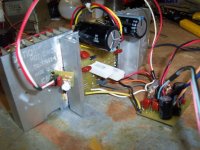
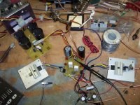
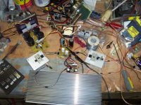
a couple of pics of the amp
here are a couple pics of the amp, and the output wave on the oscilloscope, im going to build a new board to fit the output transistors horizontally,with about 2 pairs of output transistors each. could be too much heat. but ill find out.im a try to fit may be two or three of these amps on the large heatsink.
here are a couple pics of the amp, and the output wave on the oscilloscope, im going to build a new board to fit the output transistors horizontally,with about 2 pairs of output transistors each. could be too much heat. but ill find out.im a try to fit may be two or three of these amps on the large heatsink.
Attachments
- Status
- Not open for further replies.
- Home
- Amplifiers
- Chip Amps
- i need help with this LME49810 schematic


