Hi all, i'm making the Legend Stage Master amplifier of Dr. Jagodic but i have some strange behaviors.
I'm an experienced electronics builder so, i think to have made all at good level and i already have checked many times all the circuit without find any evident problem.
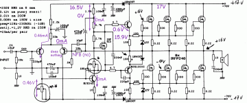
In attach you can find the circuit of the amplifier.
To be prudent, i did the first power on with 17-0-17 supply and the result are:
1. The output is at + 16V
2. Probing the gate of the mosfet of final stage i found 16V for the positive rail and -17V for the negative.
3. The trimmer to adjust the offset make the adjustment only from 16 to 14V.
4. The quiescent current, can be adjusted from 0.5mA to 6mA. Due the low supply maybe it's right but what about the offset ?
It's seems that the mosfet are working in saturation area but why ?
Could you please help me to investigate looking at the circuit ?
Maybe the supply is too low to engage the circuit ? it would be the first time, i made hundreds of amps and always did the first power on with a low supply like this. Always worked....but now ?
Please help........
I'm an experienced electronics builder so, i think to have made all at good level and i already have checked many times all the circuit without find any evident problem.
In attach you can find the circuit of the amplifier.
To be prudent, i did the first power on with 17-0-17 supply and the result are:
1. The output is at + 16V
2. Probing the gate of the mosfet of final stage i found 16V for the positive rail and -17V for the negative.
3. The trimmer to adjust the offset make the adjustment only from 16 to 14V.
4. The quiescent current, can be adjusted from 0.5mA to 6mA. Due the low supply maybe it's right but what about the offset ?
It's seems that the mosfet are working in saturation area but why ?
Could you please help me to investigate looking at the circuit ?
Maybe the supply is too low to engage the circuit ? it would be the first time, i made hundreds of amps and always did the first power on with a low supply like this. Always worked....but now ?
Please help........
Attachments
Can you try the circuit without the output stage?
Check the lower driver transistor and related connections.
Check the lower driver transistor and related connections.
Last edited:
> Maybe the supply is too low to engage the circuit ?
Yes.
Normal: 70V through 33k is 2mA. Half of that in each 'A92, so 1mA into the 1k trimmer. Trimmed about 600 Ohms, just turns-on the '340 transistor.
Under-powered: 17V in 33k is 0.5mA, so 0.25mA to the 1k trimmer. Even at max this 0.25V will not turn-on the '340, so 1.8k+4.7k pull the center-point all the way to the upper rail.
It needs to be very near +/-70V to work as designed. (It is "wrong" that the supply voltage has to relate to a Vbe drop.)
I have brought-up untested amps with a couple of 100 Ohm 10 Watt resistors in series with the rails. At +/-35V it can only pass 1/3rd Ampere or 3 Watts. So I guess those values will work to +/-70V. It will not put big power in 8 ohms with 100 ohm supply resistors. Some amps will oscillate with supply resistors, and big supply caps can deliver enough charge to burn large transistors. This amp, no-load, a good 10uFd on each rail may steady it.
And yes getting good behavior without the output devices is very wise.
Thank you for your answers. What concern me a lot is the fact that i see 16V on the gate of the output device. If the driver doesn't work due a too low supply, i shouldn't have this polarization on the gate of the mosfet.
Right ?
Right ?
I have tried to disconnect the final stage and the amplifier doesn't work. No currrent on the rails
I suspect the amp is fine just lack of current due to very low rails.
You could try it on higher rails but to be safe dont connect a speaker.
Or even use a mains series light bulb.
You could try it on higher rails but to be safe dont connect a speaker.
Or even use a mains series light bulb.
...What concern me a lot is the fact that i see 16V on the gate of the output device. If the driver doesn't work due a too low supply, i shouldn't have this polarization on the gate of the mosfet....
That is exactly what you expect when the input devices are starved and the 4.7k pull-up resistor works fine. Do arithmetic.
Attachments
That is exactly what you expect when the input devices are starved and the 4.7k pull-up resistor works fine. Do arithmetic.
Ok you convince me. I'll test with 40-0-40, with this supply it should work.
For me is enough that i can check the offset to 0 and that the quiescent current is tunable by the trimmer.
After of that i'll check with the right supply (70-0-70) and i'll start to do the real tests. I already made a 400W load with film 8 resistor mounted on radiator.
Thanks
Hi all, i did the test with 40-0-40 rails and now it works perfectly. Quiescent current is fully manageable and all the levels are ok. There is one point still not convince me:
the offset voltage doesn't go down to 96mV. I think the stage to tune the offset is very simple so maybe this is the problem but is there something i can do to push down still this value ?
Another question, i noted that in the first 4 - 5 minutes the ampli is not so stable, the offset continue to vary, not so much, but become stable only after 4 -5 minutes. I don't like this, in my other amps, the stability of circuit was reached in only 5 -10 secs. Is there something i can do to improve it ?
Thanks in advance
The output and driver transistors will heat up and the voltages across them will vary depending on how much hotter they get.
I found adding decent heat sinks to drivers as well as the outputs helped keep dc offset more stable.
I found adding decent heat sinks to drivers as well as the outputs helped keep dc offset more stable.
The output and driver transistors will heat up and the voltages across them will vary depending on how much hotter they get.
I found adding decent heat sinks to drivers as well as the outputs helped keep dc offset more stable.
They have good heat skins as suggested by the designer. But why i can't go down from 96mV ?
putting the MPSA 92 attached with glue could help ? (this should put both the transistor at the same temperature)
I had the same problem with a JLH amp.
I just increased size of dc offset pot a little.
Could be down to the low rail voltages again ?
I just increased size of dc offset pot a little.
Could be down to the low rail voltages again ?
Maybe but i think 40-0-40 is enough to works into the specs.
I suspect more a misalignement between the MPSA92 in the differential amplifier.
I suspect more a misalignement between the MPSA92 in the differential amplifier.
That would be a rather severe mismatch for BJTs.
I'd rather suspect that one of your 470 µFs is a bit more leaky than you'd like. Looks like you could remove either or both and check output offset then. Matching of your 39ks seems worth looking at as well.
I'd rather suspect that one of your 470 µFs is a bit more leaky than you'd like. Looks like you could remove either or both and check output offset then. Matching of your 39ks seems worth looking at as well.
I have substituted the 470uF with same value but bipolarized elctrolitic audio class. It seems better.
Update on the warmup. Finally i connected the amp to the power supply. All works fine! I setup 25mA for mosfet so 100mA for rail.
Offset was regulated to 2mV, very good.
Now i'm approaching the power test. I made a 400W 8ohn load for that using film armoured resistors mounted on a big heatskin.
I would to measure the max power before clipping and the frequency response.
Thanks for the help received.
I'll post also some picture at the end.
Looking at the initial posting, the issue that Alessandro experienced shows the benefits of current sources vs. resistors as active loads. Replacing the LTP 33K & 2.2k with a current source and the second stage's 4.7k & 1.8k with a current source would have led to proper operation even at +/- 17V. In this modern age where transistors don't cost that much, there is no reason for this level of minimalism.
@Alessadro: If you want to change the design to include current sources, take a look at the Honey Badger amp for a good implementation example.
Best, Sandro... but no Ale 🙂
@Alessadro: If you want to change the design to include current sources, take a look at the Honey Badger amp for a good implementation example.
Best, Sandro... but no Ale 🙂
- Home
- Amplifiers
- Solid State
- i need help with Stage Master circuit