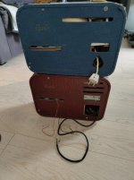
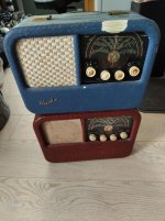
Hi, I got 2 radios from my dad that's from 1950s-1960s. It's Radionette's Kurér radios that was pretty popular in Norway back then. I wanna give them new life my putting new speakers in them and use them as speakers for my PC and phone (was thinking adding AUX input and Bluetooth if possible). I'm incredibly new to doing anything like this, the closest I've come is building PCs, other than that, everything is pretty new to me.
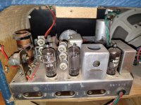
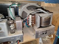
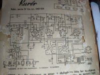
Any tips for what parts I can use (and also any tutorials that could help me?) If possible I would like to make the power and volume notch work with the new components. I have the schematics (if thats what it is called) for it but it's all in Norwegian. I can try to translate the schematics to English, but there are many of these words that I've never heard since 1960's Norwegian is a bit different and way more formal than todays Norwegian so I'll write "(?)" after a word I'm not sure if I translated correctly.

F: Foran = F: Front (or frontside)
B: Baksiden = B: Back (or backside)

"Rør- og trimmerplasering" = Rear and trimmerplacement (?)

"TRIMMING: Before you trim, look at the scaleplate(?) hasn't moved itself relative to the pointer(?). The pointer(?) is supposed to stop at the right endline of the outermost part of the scalehalfcircle(?) when the variable condensator(?) is turned/screwed all in. Sidewaysmovement(?) is controlled by rotating the pointer vertically, and then it's supposed to go through the top controlmark(?) and in the middle of the globe."

"INTERMEDIATE FREQUENCY: 455kc. These circuits are fixed(?) (or like non adjustable)"
"THE OSCILLATOR CIRCUITS are only trimmed when the scale doesn't work/isn't right/incorrect. If you don't have a crystalcalibrator(?), then you can trim close to one of the known stations, the trimfrequencies are written below:
"Shortwave(?) Trimfrequency 18Mc. Trimcondensator 1.
Fisherwave(?): Oscillator circuit is the same for Fisherwave and Intermediate wave
Intermediate wave: Trimfrequency 1300kc . Trimcondensator 2.
Long wave: Trimfrequency 300kc. Trimcondensator 3.
I M P O R T A N T ! Trim first short wave, then intermediate wave and at last the long wave."
"ENTRACE/INPUT CIRCUITS(?) are trimmed to achieve the best possible sensitivity (not to make the scale more accurate)
a measuring frame(?) is preferrably used to connect between a measuring transmitter (?) and a receiver.
Both chassis and battery must be in place during trimming of the entrance/input circuits.
short wave: Trimfrequency 15Mc. Trimcondensator 4.
fisherwave: Trimfrequency 2200kc. Trimcondensator 5.
Intermediate wave: entrance/input circuit is fixed/non adjustable.
Long wave: Trimfrequency 250kc. Trimcondensator 6.
Be careful when measuring because the batteries can easily explode."
I hope all that makes sense in English, if not then ask and I can try to provide a better translation. What parts would you recommend me use? How do I use them?
Thanks in advance.
Any tips for what parts I can use (and also any tutorials that could help me?) If possible I would like to make the power and volume notch work with the new components. I have the schematics (if thats what it is called) for it but it's all in Norwegian. I can try to translate the schematics to English, but there are many of these words that I've never heard since 1960's Norwegian is a bit different and way more formal than todays Norwegian so I'll write "(?)" after a word I'm not sure if I translated correctly.
F: Foran = F: Front (or frontside)
B: Baksiden = B: Back (or backside)
"Rør- og trimmerplasering" = Rear and trimmerplacement (?)
"TRIMMING: Before you trim, look at the scaleplate(?) hasn't moved itself relative to the pointer(?). The pointer(?) is supposed to stop at the right endline of the outermost part of the scalehalfcircle(?) when the variable condensator(?) is turned/screwed all in. Sidewaysmovement(?) is controlled by rotating the pointer vertically, and then it's supposed to go through the top controlmark(?) and in the middle of the globe."
"INTERMEDIATE FREQUENCY: 455kc. These circuits are fixed(?) (or like non adjustable)"
"THE OSCILLATOR CIRCUITS are only trimmed when the scale doesn't work/isn't right/incorrect. If you don't have a crystalcalibrator(?), then you can trim close to one of the known stations, the trimfrequencies are written below:
"Shortwave(?) Trimfrequency 18Mc. Trimcondensator 1.
Fisherwave(?): Oscillator circuit is the same for Fisherwave and Intermediate wave
Intermediate wave: Trimfrequency 1300kc . Trimcondensator 2.
Long wave: Trimfrequency 300kc. Trimcondensator 3.
I M P O R T A N T ! Trim first short wave, then intermediate wave and at last the long wave."
"ENTRACE/INPUT CIRCUITS(?) are trimmed to achieve the best possible sensitivity (not to make the scale more accurate)
a measuring frame(?) is preferrably used to connect between a measuring transmitter (?) and a receiver.
Both chassis and battery must be in place during trimming of the entrance/input circuits.
short wave: Trimfrequency 15Mc. Trimcondensator 4.
fisherwave: Trimfrequency 2200kc. Trimcondensator 5.
Intermediate wave: entrance/input circuit is fixed/non adjustable.
Long wave: Trimfrequency 250kc. Trimcondensator 6.
Be careful when measuring because the batteries can easily explode."
I hope all that makes sense in English, if not then ask and I can try to provide a better translation. What parts would you recommend me use? How do I use them?
Thanks in advance.
Attachments

UPDATE:
(idk how to edit the post so here's a little more info)
The images shown are all just from the blue radio. Here's images from the red one.
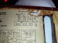
So the red radio seems to be missing the speaker. And also the schematic seems to be a little bit destroyed. I think my dad bought this second hand so that might be missing the speaker and a power cord. The speaker is 5" or 12.5cm

(idk how to edit the post so here's a little more info)
The images shown are all just from the blue radio. Here's images from the red one.
So the red radio seems to be missing the speaker. And also the schematic seems to be a little bit destroyed. I think my dad bought this second hand so that might be missing the speaker and a power cord. The speaker is 5" or 12.5cm
Attachments

The tube DL96 has very low power output and it is unlikely you find a speaker which is more suitable than the original one.
Check out Seth Arp's youtube channel - it's almost his trademark to add bluetooth to old tube radios he fixes - plenty of information in his videos for that.
https://www.youtube.com/@misterradio5035/videos
https://www.youtube.com/@misterradio5035/videos
The input called GR is probably an input for a gramophone with crystal cartridge. You can also use it as a line input and connect a Bluetooth receiver with a line output to it. You can use two 4.7 kohm resistors to mix stereo to mono, if desired.
By the way, I don't know if this is applicable, but valve equipment that hasn't been used for decades requires a special turn on procedure to keep the power supply electrolytic capacitors from exploding and power supply resistors from going up in smoke. The first step is to check whether the insulation of the wires still looks good or is falling off, like dried out rubber insulation sometimes does. If that's OK and if you have or can borrow a variac, you can very slowly increase the voltage. If not, you can connect a light bulb in series, start with a low-powered incandescant light bulb and go to higher powered bulb after some time.
By the way, I don't know if this is applicable, but valve equipment that hasn't been used for decades requires a special turn on procedure to keep the power supply electrolytic capacitors from exploding and power supply resistors from going up in smoke. The first step is to check whether the insulation of the wires still looks good or is falling off, like dried out rubber insulation sometimes does. If that's OK and if you have or can borrow a variac, you can very slowly increase the voltage. If not, you can connect a light bulb in series, start with a low-powered incandescant light bulb and go to higher powered bulb after some time.
Last edited:
Depends on what you want "beneath the surface" and how far you want to take things.
At one extreme you could restore the tubes, make the radio pick up all the correct stations, and hack the original schematics to add aux inputs for a bluetooth module and headphone jack, powering the original speakers or very similar vintage replacements.
At another extreme, you could rip out the insides and replace everything with an all-in-one class-d amplifier + bluetooth + digital radio, and only keep the box as a facade that "looks classic".
Somewhere in between it could be more interesting (IMO). If the original had enough airflow for tubes, maybe it could house a class-a MOSFET amplifier? Like an ACA or Zen variation or Udness or M2x or similar?
A laptop style PSU or embedded power supply could provide around 24V * 1A for a class-a amplifier with DC-blocking capacitors on the output. An LM317 based filter drops 4V for a net 20V, or if the current is constant, as with some amplifiers that use a CCS, a passive capacitor bank with capacitance multiplier could be used to filter out PSU noise.
It might be possible to repurpose one of the tubes for a pre-amp stage if you want to do additional research for that.
The actual bluetooth / radio modules should be fairly plug-and-play, and you might have to supply a specific voltage for them. Depending on how much development you want to do, you may be stuck with funny voices and blings when 'pairing' your phone though.
Ask 100 people, get 100 different ideas.
Does it have to be Bluetooth?
I have converted two by adding an Airport Express and a small USB powered amplifier driving the original speaker
I use Airplay to send music to them - one in each bedroom. This is an Apple solution, but there must be an Android equivalent
Brian
I have converted two by adding an Airport Express and a small USB powered amplifier driving the original speaker
I use Airplay to send music to them - one in each bedroom. This is an Apple solution, but there must be an Android equivalent
Brian
Thanks for the reply. I've asked on multiple forums just to see what people think. One person from a different forum recommended that I buy these: https://www.ebay.com/itm/185691799124 (since one of the radio is missing the speaker and power cord) and connect it to this https://www.ebay.com/itm/274395160010 . I have a third radio that works completely fine that I have bought a what they called a "4mm banana plug" to AUX and plug it in the gramophone input to keep the vintage soud, but these two other ones I want a clean new sound, I was thinking that I could have bluetooth or AUX (or both) connectivity so I can use an DAB Radio app on my phone OR spotify, since there are no active FM radio stations in Norway anymore. I will also be donating all of the old parts to this electricity workshop (idk what it is called) called Bitraf.Depends on what you want "beneath the surface" and how far you want to take things.
At one extreme you could restore the tubes, make the radio pick up all the correct stations, and hack the original schematics to add aux inputs for a bluetooth module and headphone jack, powering the original speakers or very similar vintage replacements.
At another extreme, you could rip out the insides and replace everything with an all-in-one class-d amplifier + bluetooth + digital radio, and only keep the box as a facade that "looks classic".
Somewhere in between it could be more interesting (IMO). If the original had enough airflow for tubes, maybe it could house a class-a MOSFET amplifier? Like an ACA or Zen variation or Udness or M2x or similar?
A laptop style PSU or embedded power supply could provide around 24V * 1A for a class-a amplifier with DC-blocking capacitors on the output. An LM317 based filter drops 4V for a net 20V, or if the current is constant, as with some amplifiers that use a CCS, a passive capacitor bank with capacitance multiplier could be used to filter out PSU noise.
It might be possible to repurpose one of the tubes for a pre-amp stage if you want to do additional research for that.
The actual bluetooth / radio modules should be fairly plug-and-play, and you might have to supply a specific voltage for them. Depending on how much development you want to do, you may be stuck with funny voices and blings when 'pairing' your phone though.
Ask 100 people, get 100 different ideas.
Hi Brian, no it doesn't have to be bluetooth, I just thought it would be the easiest because it works across all platforms. I have an Android so I would have to find an Android alternative in that case, but thanks for the reply, I will try to look into alternative connectivityDoes it have to be Bluetooth?
I have converted two by adding an Airport Express and a small USB powered amplifier driving the original speaker
I use Airplay to send music to them - one in each bedroom. This is an Apple solution, but there must be an Android equivalent
Thank you, I will look at some of his videos to try to learn more. Thanks a lotCheck out Seth Arp's youtube channel - it's almost his trademark to add bluetooth to old tube radios he fixes - plenty of information in his videos for that.
https://www.youtube.com/@misterradio5035/videos
- Home
- Design & Build
- Parts
- I need help transforming radios from 1958 to digital speakers with Bluetooth