hi everyone
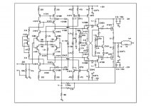
What do you think about this amp schematic?
amp schematic from japan
http://www.f8.dion.ne.jp/~isiatama/index.htm
i'll build this amp with -+70V powersupply
how to change the part? and how about this amp sound ?
please answer me..
What do you think about this amp schematic?
amp schematic from japan
http://www.f8.dion.ne.jp/~isiatama/index.htm
i'll build this amp with -+70V powersupply
how to change the part? and how about this amp sound ?
please answer me..
Attachments
If you do not have previous experience building
amplifiers from scratch, then this project is probably
too complex for you to want to start with.
I recommend that you find a much simpler schematic,
and if you choose this one, use much lower voltages.
amplifiers from scratch, then this project is probably
too complex for you to want to start with.
I recommend that you find a much simpler schematic,
and if you choose this one, use much lower voltages.
This looks messy even if one does have experience 🙂
In addition to the numerous PASS projects you'll see here,
lots of folks like the AKSA. Let's see, link is: printedelectronics.com
mlloyd1
In addition to the numerous PASS projects you'll see here,
lots of folks like the AKSA. Let's see, link is: printedelectronics.com
mlloyd1
It does look overly complicated, you can get really good results from some rather simple circuits, Zen, power-follower, and others to name a few. I'd stay away from that if it were you're first project.
thanks everybody
thanks for reply
I've already made power-follower, aleph P and more(vacum tuve,IC)
japan schematic is my next project
ps. dear nelson pass
i respect you as my leader of diy life
i suggest modifiy schematic for +-70V power supply
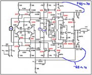
how about this schematic?
C1815,A1015 => C1775,A872
B715,D755 C2240,A970 => C2705,A1145
A1538,C3953 => C3423,A1360
power MOSfet=>BUZ903,908 X 4
CRD,firststage J-fet current sourse=> useing TR(current sourse) for high voltage
Attachments
Kurt,
This amplifier is designed with separate power supplies of 35 and 22 v. If you want to use this schematics with unique power supply of 70 v, you have to totally revise each stage. It's a hard, long and venturesome work.
Good luck...
Regards, P.Lacombe.
This amplifier is designed with separate power supplies of 35 and 22 v. If you want to use this schematics with unique power supply of 70 v, you have to totally revise each stage. It's a hard, long and venturesome work.
Good luck...
Regards, P.Lacombe.
Not too complex
I think that most of the amp is very classical but some parts are a little bit special. When you use high voltage the component choices becomes more critical. It's OK to use the same voltage but you loose rather much power. I recommed that you have stabilized voltage for the driver and unstabilized for the output stage.
You must also control the behavior when the amp is overloaded. You (can) get nasty output signals if some transistor stages are saturated. It's important that you avoid saturation.
Do you have a little bit more detailed schematic?
Mail me private or give me an URL.
I forgot to tell you that you probely have to add heatsinks in some places. Total current consumption will probely be 30-100 mA, quite hot with 140-200 Volts! You must calculate the dissipated power very carefully. You must also ground the heatsinks and this adds capacitance to the collector of the transistor. Some parts are sensitive with ungrounded heatsinks.
thanks
thank you very much peranders
you can see detail schematic on japan website
http://www.f8.dion.ne.jp/~isiatama/index.htm
if you don't read japanes then you need translation
You may use
http://babelfish.altavista.com/
for the translation in online.
thank you very much peranders
you can see detail schematic on japan website
http://www.f8.dion.ne.jp/~isiatama/index.htm
if you don't read japanes then you need translation
You may use
http://babelfish.altavista.com/
for the translation in online.
I have looked a little bit more into the amp at the japanese page (the translation service work almost perfect) and I think it's not so hard to make the amp for higher voltage. Most of the amp is standard, very much alike my own QRO amp designed for +-70-80V. Smart thing about the "laying"(right spelled?) transistors!
You must probely recalulate some stages due to high current consumption. I will look into the problem later, can't promise when.
The data of the amp is quite extreme. Veeeeeery low distortion!
You must probely recalulate some stages due to high current consumption. I will look into the problem later, can't promise when.
The data of the amp is quite extreme. Veeeeeery low distortion!
- Status
- Not open for further replies.
- Home
- Amplifiers
- Solid State
- i need help to build poweramplifier

