well these subjects are old but still valid http://www.diyaudio.com/forums/car-audio/30183-toroid-car-amp-smps.html#post369436
I usually use paralleled primary's sandwich around the secondary to help leakage L.
sometimes called interleaved
I usually use paralleled primary's sandwich around the secondary to help leakage L.
sometimes called interleaved
Manufactures uses toroids for inverters because they are thin, not because they are "better".
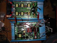
Here is a picture of a 3500W inverter with 6 EFD type transformers. This allows them to keep the case thin.
yes inverters have much higher voltage than car stuff ( stacked in series I believe so creepage is still a concern )
Infina, that looks like a fun thread, first page sounded good so i will go through it.
Dinithm, give us the construction details of your transformer. What wire size how many strands, how many turns, what layer went were on the bobbin. It looks like your bobbin is broken did you need to break it to fit wires?
Dinithm, give us the construction details of your transformer. What wire size how many strands, how many turns, what layer went were on the bobbin. It looks like your bobbin is broken did you need to break it to fit wires?
Infina, that looks like a fun thread, first page sounded good so i will go through it.
Dinithm, give us the construction details of your transformer. What wire size how many strands, how many turns, what layer went were on the bobbin. It looks like your bobbin is broken did you need to break it to fit wires?
No need to torture yourself. There are plenty of friendly applications in the web to calculate the transformer. I got one downloaded from EPCOS official web page long time ago. Software was calculating whatever you can imagine, even inflation of USA dollar in 5 years. So smart people they are. These EPCOS.

I would NOT just blindly use software either.
one or two equations in a spread sheet, creates good thinking for everyone . copper loss and wire calculation is just arithmetic anyways
that's why I always remember Volt*seconds and Ae are key for most any transformer, 50Hz to 100KHz
edit > I always remember 500 Circular Mils / Ampere too > higher or lower depending on skin depth and fill factor for about 30*C rise
Last edited:
I would NOT just blindly use software either.
one or two equations in a spread sheet, creates good thinking for everyone . copper loss and wire calculation is just arithmetic anyways
that's why I always remember Volt*seconds and Ae are key for most any transformer, 50Hz to 100KHz
edit > I always remember 500 Circular Mils / Ampere too > higher or lower depending on skin depth and fill factor for about 30*C rise
Agree! I told it from the beginning, the calculations is simple and straight forward. But if you wonna do it in proper way, do the backward calculations.
I do remember that for this particular push-pull the only thing that you can change is how many turns primary should have. 3 or 4. That is it. I played with this and that, this and that. And at the end, whatever transfromer was, the primary was 3 turns, the secondary is what you get from equation. Current density was 5 Amp, per square mm. Can make it bigger, taking into account that we run 100 KHz.
thanks for you'r advice.
I build up my circuit much better.
this is the circuit schematic after the modifications.


this is the waveform after the modifications.
output (75v+75v)3A load

according to this waveform there is small spike during turn off delay.
is it harmful to the mosfets.
I'm waiting for your reply.
thank you.
Small spikes will not destroy mosfet. In any case, if you open transistor data sheet, you see Usd max voltage. I do believe nowadays mosfets can tolerate huge Usd voltage.
Waveform looks strange to me. Is it full load? What about idle mode? Move your feedback loop control after output inductor. The goal is to stabilize Uout, not some voltage inside your power supply.
P.S nice software, by the way. But you would recommend you to use torroid transformer instead of general shape one.
P.S.S if you are happy with what you get, it is time to see how reliable power supply by torturing it with full load and monitoring parts temperature.
Hi
1) secondary turns / The output needs to be controlled by the duty cycle, not at peak V level. I don't know what voltage you are aiming for, but you will probably have to increase turns because it's at max duty cycle now.
2) Using a common mode choke reversing the windings will surely saturate the ferrite core. Use a powdered iron or another gapped core.
a saturated inductor is back to a peak detector, yes.
Last edited:
Interesting using a common mode choke in the output. Can you show us the waveform of the DC voltage. Use AC coupling on scope and 1v or less per division, so we can see any noise on the DC output. With the 3A load again..
Thank you.
Thank you.
primary waveform @ IDlE


primary waveform @ 140v 0.5A load

secondary waveform @ 140v 0.5A load
(green-befor output inductor/yellow after filter inductor)

primary waveform @ 2.5A load

secondary waveform @ 2.5A load
(green-befor output inductor/yellow after filter inductor)

primary waveform @ 140v 0.5A load
secondary waveform @ 140v 0.5A load
(green-befor output inductor/yellow after filter inductor)
primary waveform @ 2.5A load
secondary waveform @ 2.5A load
(green-befor output inductor/yellow after filter inductor)
Your primary waveforms are confusing. They look better as the load increases. One thing i noticed is that you increased the gate resistor to 120 ohms, this would cause very slow turn on. Change these resistors back to 22 ohms. also you should also put a 1k resistors from gate to source for a pull down for turn off.
As infinia said you would think the output filter would saturate because it is a common mode filter, but i see no sign that it is saturating.
I would just make the 2 resistors changes and see if it squares up your waveform.
As infinia said you would think the output filter would saturate because it is a common mode filter, but i see no sign that it is saturating.
I would just make the 2 resistors changes and see if it squares up your waveform.
Thinking a little more, the difference in waveform shape from no load to full load may be your feedback loop, it is unstable.
First change the resistors as i said above and then disable the feedback loop and see what you have.
First change the resistors as i said above and then disable the feedback loop and see what you have.
It could be helpful to show one gate-source/trace drain-source-voltage of one PowerMOSFET on both traces of your scope to get some insight of switching timing.
I suspect turn-off-switching is poor at the moment.
I suspect turn-off-switching is poor at the moment.
Interesting using a common mode choke in the output. Can you show us the waveform of the DC voltage. Use AC coupling on scope and 1v or less per division, so we can see any noise on the DC output. With the 3A load again..
Thank you.
these are the output waveforms at 2.5Amp load
without inductor

with 3mH choke

Your primary waveforms are confusing. They look better as the load increases. One thing i noticed is that you increased the gate resistor to 120 ohms, this would cause very slow turn on. Change these resistors back to 22 ohms. also you should also put a 1k resistors from gate to source for a pull down for turn off.
As infinia said you would think the output filter would saturate because it is a common mode filter, but i see no sign that it is saturating.
I would just make the 2 resistors changes and see if it squares up your waveform.
I changed the gate resistor to 22ohms with pulldown 1K
here is the waveform @idle

but with 2.5amp load

uhh we still have not progressed beyond post #3 e.g. the topology still needs to be changed to an LC output filter other wise you lose the ability to control the loop. using a common mode choke is unsuitable for the inductor , when you reverse the phase it will surely saturate.
1) A simple DC/DC converter without an LC low pass depends on Vin and turns ratio only. has low parts count, very bad regulation, hard on parts, and is unsuitable for high power.
2) with an LC output filter, the duty cycle determines the output voltage. The inductor limits secondary peak currents and is easier on parts , can use either, simple duty cycle adjustments (open loop ) or NFB (closed loop) to automatically adjust the output voltage to line and load variations.
Last edited:
Dinithm, in post 37 with 2.5A load and primary winding, we are now seeing more of a true waveform. The 120 ohm gate resistors were masking what was happening with the soft turn on and off.
I think what infinia is trying to say in post 38 is that the large spikes in the primary waveform is really reflected current from the secondary, as the common mode inductor saturates.
The common mode inductor you used is made for AC not DC so we should not be too surprised there is a problem.
I think you should buy two DC inductors and for now not worry about having them coupled. Something around 2.3mH and 3A min. working current. Also look up your capacitor and find it’s ESR value. You have to parallel capacitors until you are below .16 ohms (160 milli ohms). Then your LC filter should work.
Dinithm, I am looking the waveforms over and i am having second thoughts on what those spike are in the primary waveform. I think you should re-work the LC filter as i mentioned in my last post (unless someone comes forward with a design for a coupled DC inductor you could make). But i do not think this will solve your waveform problem.
I think what we are really seeing is a symptom of very bad leakage inductance in your transformer. The easiest way to find out is leave the common mode filter in the output and put the factory wound toroid back in and recheck the waveforms at no load and full load.
I think what we are really seeing is a symptom of very bad leakage inductance in your transformer. The easiest way to find out is leave the common mode filter in the output and put the factory wound toroid back in and recheck the waveforms at no load and full load.
- Status
- Not open for further replies.
- Home
- Amplifiers
- Power Supplies
- I need help ,SG3525 car amplifier smps