I finally bought an oscilloscope and I really need help setting up a new laser on my arcam alpha 7 & 8 CD players.
They both have a KSS240A laser.
I have not got a clue of how to use an oscilloscope and I do not see any potentiometers on the motherboard of the cd players. I basically need to see the eye pattern.
Can I ask, are both tracking and focus adjustments done with the potentiometers on the laser ?
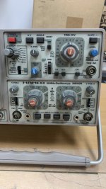
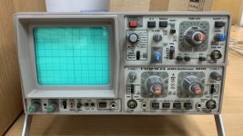
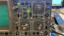
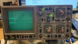
Again, I have never used an oscilloscope and I have attached photos of my oscilloscope. Any chance someone can give me some brief instructions in the same way you would do if a pilot of a plane had gone and a stranger got in his place for the first time and trying to fly it with no experience whatsoever.
So basically something like turn this knob to the right then plug this in there turn that that way etc. I do not need to know what I am doing as long as I can see the eye pattern on the screen. I have bought 5 of the same cd players so if I manage to fix one I will sort out the rest as they all have the same issue bad laser!
I did actually manage to save one as it just had smoke on the laser and by cleaning it it played like new but the other ones are very sensitive to vibrations and the laser seems to be at its end.
Thanks in advance.
They both have a KSS240A laser.
I have not got a clue of how to use an oscilloscope and I do not see any potentiometers on the motherboard of the cd players. I basically need to see the eye pattern.
Can I ask, are both tracking and focus adjustments done with the potentiometers on the laser ?
Again, I have never used an oscilloscope and I have attached photos of my oscilloscope. Any chance someone can give me some brief instructions in the same way you would do if a pilot of a plane had gone and a stranger got in his place for the first time and trying to fly it with no experience whatsoever.
So basically something like turn this knob to the right then plug this in there turn that that way etc. I do not need to know what I am doing as long as I can see the eye pattern on the screen. I have bought 5 of the same cd players so if I manage to fix one I will sort out the rest as they all have the same issue bad laser!
I did actually manage to save one as it just had smoke on the laser and by cleaning it it played like new but the other ones are very sensitive to vibrations and the laser seems to be at its end.
Thanks in advance.
Attachments
Last edited:
Wrong end of the day 🙂 but to get you started... and its easier with it in front of me... however...
Remember the scope is really just a voltmeter that traces out voltage against time.
Begin by looking at the scopes own CAL signal available from that funny looking socket thing under the screen. Set it to 1kHz and 2V
Set AC/DC/GND switches on both channels to AC initially. AC adds a cap in series with the input to block DC shifting the trace offscreen. GND removes the signal.
Set the Volts/DIV switches on both channels to 1 initially. That means 1 square on the display equals 1 volt.
Turn all the red knobs with arrows on them to the calibrate position which will be fully clockwise. They might click in the Cal position. This is the only position the settings on the switches are accurate. The knobs make each setting variable. Make sure the middle part of the volt/div knob is pushed in as that is also a switch. Look at the writing between the knobs X5 Magnification when pulled out.
Turn the Time/DIV to 1ms. That means it takes the moving spot 1ms to move one square from left to right.
Turn the delay switch to Normal.
Turn the X and Y knobs to about the middle, These position the trace.
Set the trigger switch to AC
Set the trigger level knob in the middle.
Release the CHI/CHII switch at the bottom. All four buttons 'out'
The I/II switch under the Time/DIV knob have out.
ALT and EXT buttons released.
Hold Off knob fully clockwise.
You should at this point be able to get a clear bright trace across the screen. Use a bit of wire or the probes to connect the CH1 input to the 2V Cal socket. You should see a squarewave on the screen and it should be 2 squares high with the volts/div set at 1 volt.
If you set the coupling on the input to DC you can try measuring a 1.5 volt battery. The trace should shift by 1.5 squares.
I think that's enough to be going on with.

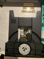
I seem to recall that one of the main failure points of the KSS240 was the lens suspension which is like a small flexible neoprene band that holds the rear of the lens assembly which apparently can deteriorate. Electrically the pickup can be fine but mechanically it is not. How big an issue that is in practice I can't really say.I did actually manage to save one as it just had smoke on the laser and by cleaning it it played like new but the other ones are very sensitive to vibrations and the laser seems to be at its end.
Checking the RF amplitude is the first step.
I need help landing a plane without having a pilots licence!
In UK you may not be allowed to jump higher than six feet without a licence. Please be careful.
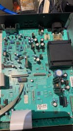
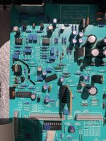
Ok I’m now set up followed your instructions. How do I check the rf amplitude. I have attached motherboard. I can see all the test points but the manual does not mention anything about that.Checking the RF amplitude is the first ste
Attachments
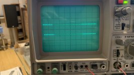
That's looking good.
The manual doesn't seem to show any front end circuitry but I would guess that Arcam just buy in a standard Sony board. I haven't any service manuals on the PC I'm on right now but any KSS240 player should be similar.
From the web...

That connector will be a ribbon. You measure at the other end where it connects to the 'front end' processing PCB.
The manual doesn't seem to show any front end circuitry but I would guess that Arcam just buy in a standard Sony board. I haven't any service manuals on the PC I'm on right now but any KSS240 player should be similar.
From the web...
That connector will be a ribbon. You measure at the other end where it connects to the 'front end' processing PCB.
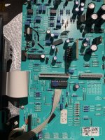
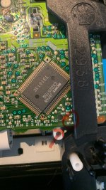
Is it cable 1 or 2 that I’m looking at. If it is no 1 it is folded underneath the cd mechanism. I cannot put a probe there while the cd is playing.
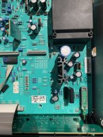
I have attached photos of the main motherboard, could it be some sort of test point there instead ?
I have attached photos of the main motherboard, could it be some sort of test point there instead ?
Attachments
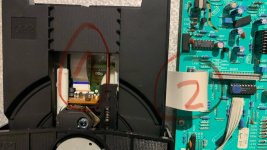
Is it cable 1 or 2 that I’m looking at. If it is no 1 it is folded underneath the cd mechanism. I cannot put a probe there while the cd is playing.
Welcome to the world of servicing 🙂
It is ribbon 1. You need to identify the RF feed from the pickup which is the same for any KSS240 player and see where it goes on the board underneath. The board is likely a Sony produced one.
I have attached photos of the main motherboard, could it be some sort of test point there instead ?
The RF is normally only available on the board under the pickup and there is usually a test point but it is often just a solder pad to probe. You are going to have to free the mech to get at the board underside.
This is from a Sony player and yours may well use the same chipset but if not simply look where the ribbon goes and identify where it goes on the board. They are not numbered here (just a spot which is probably pin 1) and so it is pin 4. O would then solder a small wire 'loop' (bit of resistor leg) to clip a probe to. Make sure nothing is shorted and then put the player into play and see what you get.
Until you are mor experienced I would remove the mains plug from the player and scope as you connect the probes. Remember if the player is mains grounded and the scope is mains grounded then you can easily short things accidently if the probe ground lead touches something it shouldn't.
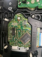
The RF point is the solder pad here. LRCK is 'left/right clock' used to identify the frames of data for each channel. Solder a little wire or whatever to the pad to connect the probe to.

Wires can bend, pins from pin header are rigid and do not move when you move the scope/DMM probes/wires around, these I usually use.Solder a little wire or whatever to the pad to connect the probe to.
Here you go:I have not got a clue of how to use an oscilloscope...
https://download.tek.com/document/XYZs-of-Oscilloscopes_Primer_03W-8605-8.pdf
https://download.tek.com/document/02_ABCs-of-Probes-Primer.pdf
In the probe document, in addition the basics of probes and their calibration, the section on probe grounding can be very important too (pp. 46-50).
A couple more questions as I have 5 x identical ARCAM 7 CD players to calibrate with new lasers.
1. If I calibrate one mechanism( laser and full cd mech ) in one Arcam 7 can I technically take the whole cd mechanism and move it to another identical Arcam cd player, in this case another Arcam 7 and expect it to work as there are not adjustments for the laser on the main motherboard?
2. If I do the calibration in one machine can I simply remove only the laser and connect it to an identical Arcam cd and again expect it to work as it should.
It will simplify my calibration process if o have just one machine that I do all the work.
Johnny, after all the help you got from people, all i can see are more questions no single "like" from you?
How come?
How come?
Last edited:
- Home
- Source & Line
- Digital Source
- I need help landing a plane without having a pilots licence!