Hi Guys.
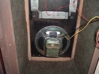
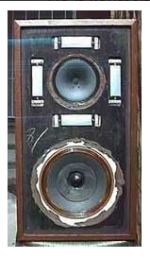
Some time ago I picked up a pair of RS Electrostat 2a speakers just to mess with. The stats sound wonderful but the woofer is really lacking in low and mid. They cross over to the stats at 5khz.
So I decided to do a radical redesign on them with parts on have in the shop and a could new woofers.
And I can build anything but I'm lost when it comes to crossovers.
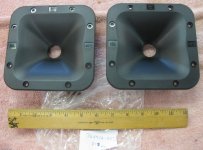
As you can see in the pix, the states are arranged in a square and that blank space in the middle is just the right size for a 6x6 horn with a Dayton Audio DT250P-8 Compression Driver.
I bought two new woofers - DynaLab V22-DR-0003 8" Paper Cone Woofer 4 Ohm that have an f3 of 25hz in a 3 cu ft box.
The current box is only 2 cu ft so I will extend the back out to get close to 3 cu ft.
The CD is solid down to 600hz out to 10khz
so I want to cross the woofer at 600hz to the CD then cross the CD at 5khz to the stats.
Once I get the bugs worked out I will build nice cabs for them.
link to woofer
DynaLab V22-DR-0003 8" Paper Cone Woofer 4 Ohm
Attachments
Last edited:
More stuff.
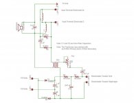
These are the horns I'm using and a pic of the crossover and power unit.
These are the horns I'm using and a pic of the crossover and power unit.
Attachments
Last edited:
I've not measured the CD with horn. A friend has my mic for a few weeks but as you mentioned it, I should measure all the drivers in box.
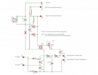
I found that crossover schematic online so I'll pull one of the crossovers and plot it out.
I'm just now finishing up building a changing table for my new grandson so I'll start on the project next week.
I found that crossover schematic online so I'll pull one of the crossovers and plot it out.
I'm just now finishing up building a changing table for my new grandson so I'll start on the project next week.
It is unusual. There are two input choices, different crossover frequencies, there might also be a difference in sensitivity. The tweeter returns through the woofer capacitor, series style.Anyway, are you sure the original crossover doesn't look closer to this?
I would want to redesign the high tension supply. Nothing special, power transformer, wiring tidied and twisted, make sure there's no HF noise. Small enclosure.
Then I'd consider shielding the audio transformer, or at least giving it a flux band and bells. Remember this may have up to 340V across it.
Consider that also when replacing capacitors.
Crossing an electrostatic is different to a dynamic speaker. It behaves electrically like a capacitor. The impedance gets low at high frequencies. Adding capacitors may act like resistors on a typical speaker.. resistors may act like inductors.
The two choices are if you have a 2a the other speaker is a 2. It doesn't make sense to me but the literature says. I plan on eliminating the one marked 2 but I'm not sure what to take out of the xover.
All good point Allen. I added them to my cheet sheet. I plan on making large xover boards so I can separate the power from the signal by distance.
All good point Allen. I added them to my cheet sheet. I plan on making large xover boards so I can separate the power from the signal by distance.
You might also consider replacing that transformer with the 3-Ohm secondary with one that has 3k-Ohm. Be sure to wear your rubber boots because there's no transformer on the bias supply.
Otherwise, the schematic is challenging to read, kind of like old telephone circuits.
Those stats might sound pretty good, but are in the same quality (and freq range) class as quartz tweeters. I think they are single-sided (??), a design derided since back in 1940. But the good news is you might not hear much HD from a tweeter crossing over north of 5kHz. Piece of cake to run REW (even with your laptop mic) and see how much HD.
B.
Last edited:
Unfortunately, there's nothing to remove for that option.I plan on eliminating the one marked 2
So L1 and L2 are part of the normal crossover?
Yep,
When connecting up this crossover through the 2a ( terminal ), both L1 & L2 are utilized.
L1 is bypassed when a person connects to the "2" input terminal.
Whether or not the ( unknown ) values of those coils will be of any use within your custom 3 way design remains to be seen.
🙂
You might also consider replacing that transformer with the 3-Ohm secondary with one that has 3k-Ohm. Be sure to wear your rubber boots because there's no transformer on the bias supply.
I guess my joke missed. The transformer you have there is a likely already a 1:100 step-up to drive the tweeters. You must have mis-read the label. Which means you can get a nasty shock from a variety of points but including that innocent looking pot when there
is a signal.
Honestly, test the tweeters for HD because what you might think is sweet during a brief test might be truly awful on extended listening. Fun to experiment but a single-sided ESLs are just historic curiosities although once not uncommon. Any cheap fried-egg tweeter would be vastly better in range and quality. Ditto for that "vintage" woofer. Ditto for the bias high-voltage doubler components.
B.
Last edited:
- Home
- Loudspeakers
- Multi-Way
- I need big time help with a crossover for a very strange build

