HPotter,
How could one get a hold of the schematic for the xover you are referring to. I have not seen or heard of them. Pictures would also be great. thanks.
How could one get a hold of the schematic for the xover you are referring to. I have not seen or heard of them. Pictures would also be great. thanks.
In my bi amped system, I am going to put a passive L/C filter in front of a BOSOZ...whats wrong with that idea?
HPotter
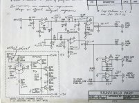
What is the note referring to the * cutoff at the top of the page?
Also, what does the line above the word "stage" say?
Finally, do you have any other info that goes with this unit/schematic (adjustment procedure/specs, voltages, etc)?
Thx,
Steve
What is the note referring to the * cutoff at the top of the page?
Also, what does the line above the word "stage" say?
Finally, do you have any other info that goes with this unit/schematic (adjustment procedure/specs, voltages, etc)?
Thx,
Steve
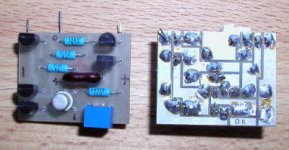
8 resistors with * are in a plug in module. Caps values in ( ) are for frequency x10. The numbers beside op amps in triangles are for offset adjustment sequence. Voltage is +/-15V. THD is .01%, slopes 18dbs, inp imp 20k, output 1k5 ohms.
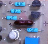
Resistors values for 90Hz are 39k ohm, for 160Hz - 22k ohm, for 904Hz - 3k9 ohm. I guess from that you can calculate any other frequency. All 8 resistors have the same value.
Resistors values for 90Hz are 39k ohm, for 160Hz - 22k ohm, for 904Hz - 3k9 ohm. I guess from that you can calculate any other frequency. All 8 resistors have the same value.
Good xover
I purchased a Behringer CX3400 stereo 3-way crossover from www.zzounds.com for $149. It is a 24db/octave Linkwitz/Rilex design. A friend also has purchased the same crossover and is very happy with it. They also have the Behringer CX2310 with is the 2-way version for $99
I purchased a Behringer CX3400 stereo 3-way crossover from www.zzounds.com for $149. It is a 24db/octave Linkwitz/Rilex design. A friend also has purchased the same crossover and is very happy with it. They also have the Behringer CX2310 with is the 2-way version for $99
Up to now I read several opinions in this thread about about all kinds of filter topolgy and their properties and which one to choose for best results: 6dB, 24dB, 48dB, sums to perfect phase, substraction or not substraction etc., etc.
Sorry, but discussing this without the particular speaker in use is meaningless.
The electrical property or the topology of the filter itself does not matter.
What counts is what comes out of the speakers.
Wether good results are obtained regarding the final ouput is not a question how perfect the filter works by itself but how perfect the filter works in COMBINATION with the speaker.
So, the question which kind of filter to choose, be it 6dB or 48dB, Butterworth or Linkwitz, active/ passive or whatever depends in first regards of the particular behaving of the speaker and is not a fundamental solution fitting for all kind of speaker/crossover combinations.
There is no "good crossover" and therefore cannot be designed by itself. There is only good crossover/speaker combination.
Cocolino:
I'm afraid your logical advice is in vain. In this thread, they are too busy discussing subjective colorations of the circuits. Even the mention of opamps in the signal path are taboo to some people here. Non linear and IM distortion is apparantly desireable, over an adequate slope to some even since it avoids that use of a 'nasty' active cascaced filter. LMAO.
Good luck convincing them to be rational.
-Chris
-Admitted user of a cascaded op-amp filter on Focal mids - And Proud of It!-
cocolino said:
Sorry, but discussing this without the particular speaker in use is meaningless.
There is no "good crossover" and therefore cannot be designed by itself. There is only good crossover/speaker combination.
Yahoo! About time this came out. Look at it this way, all you're doing with an active crossover is moving it... from attachment directly to the loudspeakers to between a preamp and a power amp. What this means is that it must be designed IN CONJUNCTION WITH THE LOUDSPEAKER just as you would a passive crossover.
Linkwitz has lots of lovely information on his web site about this and all the bits and bobs that are needed. Try www.linkwitzlab.com
He even has facsimiles of his Wireless World articles that discuss all this in the 1980s.
I gotta drop this in here... There ain't nuthin' new under the sun.
regards, Keith
CHRIS8,
Just because <i>you're</i> happy with garbage op-amps dosen't mean someone else can't hear the difference. What is your reasoning for thinking there is no way to build an active filter that is both simpler <i>and</i> won't produce IM and nonlinear distortion? Or, are you just spouting off your opinion based on your objectivist viewpoint? I tend to listen with my ears, not my test equipment. So, sue me! I like music that sounds like music.
Cocolino,
I agree completely- it has to match the drivers in your system, or it will sound like garbage.
The active crossover is much easier to design and apply than passive one in the loudspeaker. It will maintain greater precision over filter characteristics than is likely with a passive system. This is because the active crossover, unlike the elements of a loudspeaker's passive crossover, is unaffected by the varying impedances of the loudspeaker drivers or the associated attenuators used to adjust their relative efficiencies.
It is true that you have to adjust crosssovr frequencies and slopes for ea. driver and match them together, but it is more fun and much easier than playing with passive components inside the loudspeaker.
I guess it is always advisable to choose whatever works for you and makes you happy. If you like op-amp why not to use them?
If you feel that complicated networks work better for you, use them. I, OTOH always chose to use the simplest way (even when building a chassis)😉
SteveG:
Re: this paragraph
I'm afraid your logical advice is in vain. In this thread, they are too busy discussing subjective colorations of the circuits. Even the mention of opamps in the signal path are taboo to some people here. Non linear and IM distortion is apparantly desireable, over an adequate slope to some even since it avoids that use of a 'nasty' active cascaced filter. LMAO.
The IM and non-linear distortion referred to here is a property of the speaker, not the crossover. A faster crossover slope reduces cone excursion and reduces this distortion.
You have a lot more freedom woth active crossovers.
It´s a lot cheaper to swap in and out caps and resistors in an active XO than in a passive. Plus you can control phase changes, time alignment, Q specially in the low ernd and so on.
Experimenting with hi grade passive parts costs a fortune.
It´s a lot cheaper to swap in and out caps and resistors in an active XO than in a passive. Plus you can control phase changes, time alignment, Q specially in the low ernd and so on.
Experimenting with hi grade passive parts costs a fortune.
promitheus said:You have a lot more freedom woth active crossovers.
It´s a lot cheaper to swap in and out caps and resistors in an active XO than in a passive. Plus you can control phase changes, time alignment, Q specially in the low ernd and so on.
Experimenting with hi grade passive parts costs a fortune.
exactly the rationale behind John Pomann's Active XO Experimenters Kit.
dave
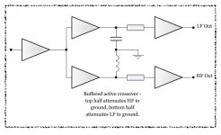
I just had this idea for an active crossover that has no phase incoherency - it's probably flawed as I only have very basic knowledge.
It's basically just a series of buffer stages (optionaly with gain control to equalise) that have either a low or high frequency low-impedance ground connection.
As I say it's really basic - so much so that it's probably seriously flawed.
<center>
🙄
</center>
One advantage I could think of is that it could be op-amp based for simplicity or fully discrete whatever you prefer.
Please don't laugh if it's a stupid idea
<center>
Attachments
...also I'd be happy to render circuit diagrams for people on the forum - I get my fair share of advice for free so it's the least I can do for you guys.
<center>
😉
</center>
All I ask is that you don't send me any huge Krell wannabes!
...simple amp circuits, crossovers, etc I can do - all symbols are custom drawn so I'm versatile.
I kind of hoped my renderings were professional looking - at least better than hand-drawn.
<center>
😉
</center>
All I ask is that you don't send me any huge Krell wannabes!
...simple amp circuits, crossovers, etc I can do - all symbols are custom drawn so I'm versatile.
I kind of hoped my renderings were professional looking - at least better than hand-drawn.
- Status
- Not open for further replies.
- Home
- Loudspeakers
- Multi-Way
- i need and GOOD active XO