i "need" to build a headphone amplifier and im limited to these active components, the headphones(iem's) i want to drive are the kinera celest gumiho, the issue i have with them is that theyre 8ohms and my dongle cant keep up current wise during the bass notes.

You don't need a virtual ground, the LM-386 just uses a single supply.
You can use a 9V battery as the single supply, see fig. 9-1 in the LM-386 data sheet.
The LM-358 is not suitable for driving your headphones, or any low impedance.
You can use a 9V battery as the single supply, see fig. 9-1 in the LM-386 data sheet.
The LM-358 is not suitable for driving your headphones, or any low impedance.
i know i dont need a virtual ground but i also dont want an output cap i also dont need the 750mw/1w that the lm386 can provide
If you make the output capacitor big enough, it won't be a problem. Around 2200uF at 16V (or more uF) will be fine.
Otherwise you don't have any other suitable parts.
Otherwise you don't have any other suitable parts.
i have bd911/912 and bd135/136 transistors that i can use along side with some small signal transistors such us bc547 and 557
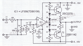
Then maybe you can rig up an op amp front end with complimentary bipolar outputs.
But you'd have to design the circuit. Something along these lines, adapted for your parts.
You'd use two 9V batteries, not one.
But you'd have to design the circuit. Something along these lines, adapted for your parts.
You'd use two 9V batteries, not one.
Attachments
Last edited:
A "splitter" will affect the sound more than an output capacitor.
It's a whole extra amplifier circuit, in series with the headphones.
It's a whole extra amplifier circuit, in series with the headphones.
oh yeah so i should just go output cap on this one i think i made a simmilar thing some time ago(just the schematic)
That way you can use the TDA2822 as well.
See figure #1, https://www.st.com/resource/en/datasheet/cd00000134.pdf
See figure #1, https://www.st.com/resource/en/datasheet/cd00000134.pdf
i personally have this thing which basically is the tda2822m application plus power supply and all i can say is that its trash

i tried this tda thing and it haves heaps of noise..
Your TDA2822 pcb should have a DIP socket so that you can check the DIP voltages before you plug in the chip. That is normal practice for these little DIY amplifiers. Also there should be a volume control pot on the PCB close to the TDA so noise pickup is minimal. It should get music from the line output of a HiFi or portable player.
You need to provide a schematic or a diagram of your gear so that people can answer questions about it. A photo is not sufficient evidence.
Hi ,noise distortion and more
What is the origin of resistors, capacitors and those other components?
- Home
- Amplifiers
- Headphone Systems
- i "need" an headphone amp ASAP
