With your method and a 1K load, I get 61.4 ohm for a signal of 2V pp.
If you already start from a non-infinite load, the incremental change will probably be even smaller than that, due to non-linearities.
If you use very small voltages, you will probably get back to the Bode results
If you already start from a non-infinite load, the incremental change will probably be even smaller than that, due to non-linearities.
If you use very small voltages, you will probably get back to the Bode results
First I put a 100 uF capacitor at the output to remove the DC.
I used load resistances 1k and 500 ohms. Output voltages were 619,7 mV (rms) and 589,0 mV and output currents 619,7 uA and 1,178 mA respectively.
This gives output impedance = 55 ohms.
I used your method for one of my EL509 SE circuit that has calculated output impedance of 1.1 ohms, but with your method Zout was 23.1 ohms.
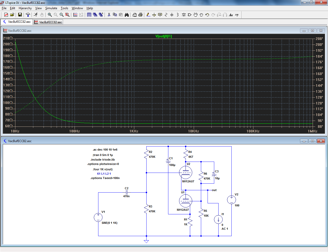
I used your method with 10mV^ signal: the impedance returns to ~65ohm, so it it is correct.First I put a 100 uF capacitor at the output to remove the DC.
I used load resistances 1k and 500 ohms. Output voltages were 619,7 mV (rms) and 589,0 mV and output currents 619,7 uA and 1,178 mA respectively.
This gives output impedance = 55 ohms.
I used your method for one of my EL509 SE circuit that has calculated output impedance of 1.1 ohms, but with your method Zout was 23.1 ohms.
The discrete method gives results highly sensitive to the non-linear component of output impedance.
This in itself gives information about the linearity (or lack thereof) of the circuit, but it is probably simpler to evaluate it by looking at the THD variation when loaded and unloaded: the delta will be realistically diluted into the main signal.
Can find any explanation why real Zout is 1.1 ohms but your method gives some 24 ohms.
View attachment 6P45S_6SL7_SE_fixbias_HIFI_CCS.asc
View attachment 6P45S_6SL7_SE_fixbias_HIFI_CCS.asc
I don't have your tube libraries but anyway, you may not use two AC1 sources to make the analysis: they will interfere with one another and the results will be worthless.Can find any explanation why real Zout is 1.1 ohms but your method gives some 24 ohms.
View attachment 314847
You simply have to leave active the stimulus source for your impedance measurement.
I attached the Spice model of the output tube and you have the model for 12AU7, so you can also simulate this circuit if you want.
The input voltage source was set to zero, so it has no effect.
I have also tested with input source remeved. Same result.
The input voltage source was set to zero, so it has no effect.
I have also tested with input source remeved. Same result.
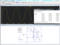
When properly measured, I get ~3.9ohm Zout @ 1KHz. Residual differences are probably mostly down to the non-linearity of the circuit, and a little to the triode different of yours.
What you call "real impedance" is not very proper, because when you load your circuit, you create additional harmonics. When you make your delta U, they take a disproportionate importance if you use the rms value.
A better method might be to compare the fundamental amplitudes, but even then, I am not sure the result will be very orthodox.
The small signal method gives a pure linear impedance, free from non-linear effects.
Non-linearities should be estimated separately, using proper tools.
That's my opinion anyway, I think it is best to decouple parameters as much as possible.
The problem is the same if you try to measure the resistance of a semiconductor diode using a simple ohmmeter: the value you get is meaningless, because the I/V characteristic is highly non-linear. You have a comparable problem here when you push the circuit into non-linear conditions
Attachments

I just know that I use this "two loads" method to determine the actual amplifiers I have built. I run them with 8 ohms and 4 ohms loads at the linear region and calculate the Zout. The results I have got with LT Spice are quite convergent with actual measured values.
I have to study this more. It would be very useful, if this worked right.
Thanks for discussion.
I have to study this more. It would be very useful, if this worked right.
Thanks for discussion.
That is normal: if you use good models on a good simulation program, results will be very much convergent.I just know that I use this "two loads" method to determine the actual amplifiers I have built. I run them with 8 ohms and 4 ohms loads at the linear region and calculate the Zout. The results I have got with LT Spice are quite convergent with actual measured values.
You measure the same parameter in both cases, but naming it properly is not straightforward: it is a mix of all values comprised between small signal and the peak value of the test signal.
If the DUT is linear, that's not a problem, but with highly non-linear circuits, huge discrepancies appear.
In semiconductor amplifiers, you can sort that out easily: you DC-couple it, and apply some fixed DC level at the input to make the Bode analyzis.
That way, you can follow the evolution of the impedance as a function of the level, but I mean a unique unequivocal level: not a set of values comprised between Amax+ and Amax-.
With a tube amplifier, where everything is AC-coupled and with transformers in the way, that is much more difficult to do accurately and rigorously.
That is certainly possible using ideal spice elements at some places, but you have to be careful to make everything as it should be because it won't be intuitive and straightforward at all, and the schematic you use for that particular simulation will be completely different from the regular one.
Anyway, I am not certain it has a great interest.
If you want to evaluate the impact of the non-linear output impedance, using a current source at the output as a stimulus is probably the best option: it will show the pure contribution of that aspect to non-linearity.
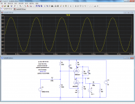
Here is what the method gives on the circuit for the OP (let's not forget him!!!).
Even at the 100µA^ step, there is already significant THD, because here we look purely at the output impedance non-linearities, undiluted.
Even at the 100µA^ step, there is already significant THD, because here we look purely at the output impedance non-linearities, undiluted.
Attachments
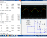
This example has an output impedance of ~65Ω.
With this tube and voltage, it is probably difficult to do much better.
Hi Elvee
I've just found this thread.
What modifications I would need to do to your 12au7 buffer schematic
to use it with a 50 Volt dc power supply ?
diyAudio
Thanx
Paul
Last edited:
What modifications I would need to do to your 12au7 buffer schematic
to use it with a 50 Volt dc power supply ?
I don't think that is possible. Even 100V is on the low side.
However, if you have a -50VDC along with a +50VDC supply, you could feed the bottom tube with the -50V (instead of ground, resistors R1, R3 and R5's ground connection would now go to the -50VDC supply) and the top tube with +50V instead of the 100VDC. .
And you could use a centertapped 70VAC secondary of a power transformer feeding a bridge rectifier, and 2 filter caps tied to ground, and the minus end of the -50V cap goes to the - end of the bridge, and the + end of the +50V cap goes to the + of the bridge. I'm guessing you wanted to avoid shock hazards from a 100VDC supply, so a pair of 50V supplies is less hazardous. But managing shock hazards is not hard, respect it but don't fear it. One hand in your pocket, to avoid shock currents going thru your heart area of your body.
Last edited:
Hi
I've simulated that circuit with LtSpice, using a load of 10k ohm, the low limit seem to be 80 volt.
Thanx
Paul
I've simulated that circuit with LtSpice, using a load of 10k ohm, the low limit seem to be 80 volt.
Thanx
Paul
Last edited:
Sorry for the late response, I am not following this thread.Hi
No reply ?
Thanx
Paul
Anyway, Wa2ise said the essential.
These tubes are not intended for low voltage operation, and starving them further won't bring any good, as you have noticed.
With adaptated values, the same principle could be used with any tube, included those intended for battery operation.
I guess that with suitable devices, operation at 12V could still be possible
Even at 50V, it is still possible to obtain decent performances. R1 has just been adapted, to avoid taking the tubes too far into positive bias.
It is capable of putting out 20Vpp into 10K with a 50V B+, at a decent THD level.
Going much further than that is not going to be possible, since the bias current is only 1.3mA.
Using even a mildly more suitable tube, like the 12AT7 things improve substantially: now, the circuit delivers 25Vpp into 7K with less than 0.05% THD.
With a really suitable tube, like the 6DJ8, even better performance would be possible.
I am unable to simulate it, as the circuit runs into convergence problems. Time for real world experiments...
Attachments
Hi
I've look today into my parts, I have a transformer good to do it at
80 volt dc power supply.
Thanx
Paul
I've look today into my parts, I have a transformer good to do it at
80 volt dc power supply.
Thanx
Paul
Hello Elvee
I've bring the 12au7 buffer preamp (mine use 100volt like in your schematic) at my musician friend home for christmas (it was my Christmas gift for him), we try it and even with a japanese amp the sound was more organic with a better sound-stage.
This 12au7 buffer preamp are very good, I think I will made one for myself.
Thank again for the schematic.
Bye
Gaetan
Last edited:
For the record (and for Andrew), this topology is called Taylor/White (Or so I think: in case I am wrong, I'm sure plenty of kind members will rush in to correct me 😀)
Hello
How can I use this vac buffer at the output of a voltage output dac (wm8741) ?
Thank you
Bye
Gaetan
How can I use this vac buffer at the output of a voltage output dac (wm8741) ?
Thank you
Bye
Gaetan
Last edited:
- Status
- Not open for further replies.
- Home
- Amplifiers
- Tubes / Valves
- I need a tube buffer circuit using a 12au7