one by one;
the EFFECTIVE current trhow the lamp at 82V AC rms (or 82 DC) is 5 amps. This means there is a current value of 5 amps RMS trhow the lamp at full rated power (410 W). But if you check the current in the oscilloscope, you will see there are peaks higer than 5 amps, so a absolute max 5 amps fuse will burn.
"it just limits current?" Diodes do block current in one direction, and drawn the current in the other. The stated max amps throw the diode is not the value the diode will limit currents to, is the point at where if you go farther, the diode will burn. Do not make more current to be drawn trhow the diode than the max stated to that diode, else say bye bye to the diode.
I would say your cheap voltmeter does not read TRUE RMS values. So do not take the reading on the lamp after the diming controler as a true value, just a reference. If it was TRUE RMS it would be labeled as that in the voltmenter, in that case the measuremnt is much closer to reality.
yes: 5 Amps average
Right: The average current through the lamp should be 5 Amps, but the peak current will be much higher. That is why you have to use a slow blow fuse.
On the other hand, the only way you have of getting 5 Amps flowing through the lamp is to turn the dimmer up slowly until the fuse blows! Then you know that the last dimmer setting delivered a bit more than 5 Amps. But that is a horrible way of regulating the current:
1) It may take more than 5 Amps to blow the fuse, since they are not that precise.
2) The "discovery process" is just as likely to blow the lamp filament as the fuse!
Get the diode in there, or you will just be wasting fuses and lamps.
On another topic, dimmers do something pretty strange: The AC line voltage is going from 0 to +166 to 0 to -166 to 0, 60 times per second (US standard). If you plot the voltage over time, you will see a sine wave. During each half cycle, a very small capacitor is charged through a resistor. The dimmer acts as a voltage-sensitive switch. When the voltage across that capacitor reaches a particular value, the triac in the dimmer switches on so current can flow. That trigger voltage can be adjusted with the dimmer potentiometer (ie. the knob). So you get sine waves out that have part of the wave clipped off. But not the top part, like you would think! Instead, the clipping occurs at some point into the half cycle. So you would see part of a sine wave with one edge almost vertical, if you put the output voltage on an oscilloscope. (That very steep edge is why dimmers introduce lots of noise into the power lines.) Trying to measure the voltage output by a dimmer is very tricky, because the the waveform is so strange. Your voltmeter will be pretty much useless.
parallel diodes
Just for Rox:
Power diodes are not perfect switches: They have some resistance in the forward direction, and that makes the forward voltage drop increase as the current goes up. (Even the leads contirbute some resistance!) The diodes will not perfectly divide the current, because they will have slightly different resistances at each forward voltage. So you are right that one will flow more current than the other.
But from a practical point of view, you can use a pair of exactly the same type of high current diodes in parallel. If you look at a plot of the forward voltage drop versus current, you will see that the voltage drop increases pretty smoothly as the current increases. Each diode will have a similar curve, but pushed a bit to the left or right. The diode that has a lower forward drop will flow a bit more current than the other, but they will be pretty close.
I would not do it with different types of diodes.
mmm, i don´t mean the internal resistance tolerances making diodes work diferently.... my goal was that this graphic displacement you was triyng to show me can make one diode work in much harder conditions than the other....
I don´t know how to xplain it but this is same problem with leds. Tho leds in paralell is not welcome, it was one of the things i learned firmly. (my teacher used to say that if you can´t xplain it, you really didn´tunderstood 😀, well, he didn´t consider the language problem 😀)
diodes in parallel=not very good idea
diodes in antiparalell=no problem at all (this is tipical for some cases we need this)
http://www3.telus.net/chemelec/Projects/Diodes-in-Parallel.htm
http://www.powerdesigners.com/InfoWeb/design_center/articles/Diodes/diodes.shtm
at bottom on this second one...
parallel diodes, again!
Thanks Rox,
The section at the bottom of your second webpage reference shows exactly what I proposed. If you used exactly the same type of diode, then you can increase the total forward current. (They call that "matching".) They give you a drawing to show the potential problem with unmatched diodes:
"Figure 12 shows exaggerated characteristics to highlight the variation in current through each diode." (My underline)
The theoretical forward PN junction voltage drop across a silicon diode is about 0.6 volts (germanium is 0.2 volts). But the silicon not at the junction and also the component leads also have a certain amount of resistance. If the two diodes are exactly the same type by the same manufacturer, that extra resistance will be very close to the same. If you had "perfect" diodes with zero resistance, then a slight difference in the forward voltage drop would send all the current through one diode, and blow it up.
But they are far from perfect! Looking at some 1N5404 datasheets, I see that they drop about 0.9 volts at 2 Amps and 1.0 volts at 3 Amps. For the sake of simplicity, lets assume that each diode has a linear relationship over that range. Let's think about what would happen in the various cases:
We want to get 5 Amps from the pair, so the combined current will be 5.0 Amps. If they were perfectly matched, then they would each pass 2.5 Amps with a forward voltage drop of 0.95 volts.
If instead one diode passes 5% less current per volt and the other diode passes 5% more current per volt in that range, then one will pass 2.625 Amps, and the other will pass 2.375 Amps. Not bad, since they are 3 Amp diodes.
If they differ by plus and minus 10%, then one will pass 2.75 Amps, and the other will pass 2.25 Amps. Still okay.
If they differ by plus and minus 20%, then one will pass 3.0 Amps, and the other will pass 2.0 Amps. This is the limit we can accept for this circuit.
I picked 3 Amp diodes precisely so it would sitll work with a huge amount of variation between them. If you actually measured the difference between two of these 1N5404 diodes from the same mnaufacturer, I think you would find no more than plus and minus 5% difference. Not plus and minus 20%.
The resistance of the non-junction silicon and the component leads is acting like the load-matching resistors they show in Figure 12.
thanks guys, now i've got something to chew on. i'm going to do it right eventually; will order the right diode in a few weeks. with four boys, christmas broke the bank this year!!!
one more question if you would- why the 1.2 ohm resistor in the diagram i posted earlier? should i include this in my circuit?
thanks and Happy Holidays!
BadBoy 😎
one more question if you would- why the 1.2 ohm resistor in the diagram i posted earlier? should i include this in my circuit?
thanks and Happy Holidays!
BadBoy 😎
old tech
The 1.2 ohm power resistor is a 1950's way of implementing a dimmer! When you switch it into the circuit with the switch (near the "10" in your drawing), then the total resistance goes up, the current goes down, and some of the power is dissappated by the resistor instead of the lamp.
Forget it! Just use your dimmer instead.
mmm, the resistors are introduced for matching purposes only. It is not the internal resistance "representation".
you are working the % as if thediodes were lineal, I believe the % in the current on same manufacturer's two diodes is much more than your sugestions.
I will take one datasheet and try some real calcs, later, no time now. This will be funny :d
you are working the % as if thediodes were lineal, I believe the % in the current on same manufacturer's two diodes is much more than your sugestions.
I will take one datasheet and try some real calcs, later, no time now. This will be funny :d
No luck, I haven´t found a datasheed with stated tolerance for tipical diodes...
This is not what we are discussing exactly but you can have an idea of what I mean; (I would have prefered to be goneral purposse diodes but, it is what i found)
http://www.ortodoxism.ro/datasheets/central/1N5239B.pdf
those are zener diodes. The stated tolerance is 5%. So the nominal volts value being X at 20ma rated current, the real volts value can be any value inside the X-0.05X---X+0.05X range.
This way if we have two zener diodes from this manufacturer, the worst case could be this one;
stated volts at 20ma is 2.4 volts.
zener a)2.28volts at 20ma
zener b)2.52volts at 20ma
then if you conect them in parallel, the a zener will drawn much higher current value. maybe twice the b zener current, this is because of the non lineallity of the curves (small volts increase means big current increase).
sorry for the offtopic example, but it does work with general purposse diodes as well. If you find a datasheet where tolerance is stated, or even better, the max and min tolerance graphic are ploted (so all diodes are inside the two graphics) this will be very welcome.
well, no diode tolerances found yet, but let me try with this explanation;
This is a general purposse diode datasheet, 3 amps stated.
http://www.fairchildsemi.com/ds/1N/1N5401.pdf
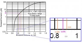
Check the graph on the datasheet (page 2), attached fille also shows in detail.
This is typical diode curve for that manufacturer, they all will be somewhere close to that curve. Check the stated 3 amps current is for a 0.875 volts drop on the TYPICAL diode.
Now let me assume 5% tolerance here;
0.875+-5%=====> 0.831 to 0.918 volt range.
I looked on the graphic and drawed the lines for 2 amps and 4 amps. This is rougly the 5% tolerance I was talking about.
If you rest 0.91-0.825=0.085 volts difference, Now this volts diference is changing from 2 amps to 4 amps on a typical diode.
if you work out 2 amps/0.085 volts, this means 23,5 amps per volt increment near 3 amps working zone.
This is why paralelled diodes are not welcome. You don´t certaily know which diode is really working. It can work fine, but it can be a disaster also. Do not go this way 😀. Buy a stronger diode.
This is a general purposse diode datasheet, 3 amps stated.
http://www.fairchildsemi.com/ds/1N/1N5401.pdf
Check the graph on the datasheet (page 2), attached fille also shows in detail.
This is typical diode curve for that manufacturer, they all will be somewhere close to that curve. Check the stated 3 amps current is for a 0.875 volts drop on the TYPICAL diode.
Now let me assume 5% tolerance here;
0.875+-5%=====> 0.831 to 0.918 volt range.
I looked on the graphic and drawed the lines for 2 amps and 4 amps. This is rougly the 5% tolerance I was talking about.
If you rest 0.91-0.825=0.085 volts difference, Now this volts diference is changing from 2 amps to 4 amps on a typical diode.
if you work out 2 amps/0.085 volts, this means 23,5 amps per volt increment near 3 amps working zone.
This is why paralelled diodes are not welcome. You don´t certaily know which diode is really working. It can work fine, but it can be a disaster also. Do not go this way 😀. Buy a stronger diode.
Attachments
diodes
First of all, yes, zener diodes are completely inappropriate since they use the reverse breakdown voltage instead of the forward voltage drop we are discussing. There is enormous variation in reverse breakdown voltage. I think they make zeners first, and then sort them into different voltages. So you can buy whatever tolerance you need. If the zener diode datasheet says their tolerance is 5%, then that just reflects how many bins they sorted them into!
As for the general purpose power diode you used for the curves, I think you are applying the dubious "zener 5% variation" value to the wrong voltage. We know that the PN junction will contribute a 0.6 volt drop, and the resistive properties of the diode will contribute the rest of the voltage drop. When you apply + and - 5% to the total voltage drop, you are also applying it to the PN junction. I think you should really apply it to (0.875 - 0.6) volts, since the PN junction voltage drop is an inherent property of a silicon diode. (It can't be changed by a process variation.) If you accept that, then your 5% variance is really plus and minus 18%!
But the 5% value is a complete fabrication! Neither one of us found a tolerance value on a 3 Amp 400 PIV silicon diode datasheet. I think the only way to know the answer to this question is to go down to Radio Shack and buy a pair of the diodes. 😀
well, in the link I posted, the typical volts @ 3 amps trhow diode is 0.752 (from graphic) but on the first page, the stated (max?) forward volts is 1.2 volts. So Somehow I am understanding a very wide tolerance here. Because a typical diode from this manufacturer will drawn 12 Amps at 1.2 Volts 😀.
You are right on the tolerances, I was just assuming the same from zeners, no idea really (but id doesn´t mean it is better than 5%, just have a look at the 1,2 volts stated... typical current I mentioned)
But trust me, diodes and parallelling is not a good idea by "construction".
You are right on the tolerances, I was just assuming the same from zeners, no idea really (but id doesn´t mean it is better than 5%, just have a look at the 1,2 volts stated... typical current I mentioned)
But trust me, diodes and parallelling is not a good idea by "construction".
http://www.onsemi.com/pub/Collateral/1N5400-D.PDF
new example, this time ensuring the stated forward volts @ 3 amps is the MAX spec; 1 volt.
the typical forward volts is not detailed on first page as the one mentioned but you can check on the tyipical diode curve @ 3 amps; somewhere 0.9 volts.
Now if we check the 1 volt value for a typical diode..... somewhere 10 amps is the current.
Now let me play something more with numbers 😀;
let's define tolerancy as the % from typical stated forward volts at rated current (0.9) to max stated forward volts for a random diode (1 volt); 0.9+0.9*X=1 where X=0.11=11%
this 11% tolerance causes 3X current increase, and it is not the worst case since we are comparing the typical Vs the MAX case, If i would compare the MIN case VS MAX case..... 😀 😀 😀.
I guess you have started questionenting about the diodes and paralelling them... 😀
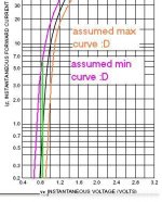
still plaiyng with numbers and montains of assumtions ;D.
the max curve on the image was assumed with V=1 @ 3 amps criteria, just moved the curve horizontally (why horizontal?... yea could be moved vertically or diagoally at any angle... well lets assume something as drawn 😀)
the min curve was drawn with no criteria, just something simetrical at the other side... 😀. (montains of assumtions yea 😀)
We want 3 amps*2=6 amps.
So this is the worst case (min Vs max)
total amps=min diode amps + max diode amps=6 amps.
the paralelled diodes will run at 0.82 volts moreless, the min diode current will work near 6 amps and the max diode current will work near zero value, yea, the system will aparently work at 6 amps, but the reallity is that only one diode is working, it will last some seconds before the diode burns (both).
This was a streme case, but two tipical diodes will work in very diferent currents, and any increment on one of them will burn the diode since we are making them work in their limits.
Nothing more to coment, this is general knowledge for electronics, paralleled diodes, zeners, leds... are not welcome 😀.
Attachments
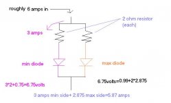
😀, you thought it was enough 😀, it is not 😀.
just thinking about how a series resistor solves that problem;
let's keep the exact two diodes on the last example, the assumed max and min diodes.
After rough calcs I worked out this circuit (attached)
The strongly mismaching diodes are now working on a very close conditions (3 amps and 2.8 amps) it is not 6 amps total, but this resistor helped setup is much better than the "erroneus" paralelles one.
Obiously, there is a wasted power on this setup because of the resistors (like 36 W wasted at all :S) also the volts drop must be considered going this way.
But the final conclusion was to show how simply paralelled diodes do not work fine and series resistors and then paralelled diodes do work better. Anyway, If i were you, I would buy a single more powerfull diode. Good luck.
Attachments
power diodes are not zeners or signal
I agree completely for the cases of zener diodes or small signal diodes: They work with such small currents that the junction drop is the only thing that matters.
But power diodes are so far from perfect that their resistance does matter. (I have designed and built a high current switching supply where the resistor we used for current-sensing was a piece of power diode lead wire!) We also had to use big Schottky diodes because standard silicon power diodes are too inefficient (too much resistance).
At 3 Amps, the 1N5404's internal and lead resistance is around 0.133 Ohms. At 2 Amps, the resistance is around 0.15 Ohms. This resistance makes two parallel power diodes work just like the load balancing circuit you posted.
The manufacturing process uses a particular size of contact and lead, which determine that resistance. They just will not vary from one diode to the next enough to make one have 0.15 Ohms and another have 0.133 Ohms at the same current. Same for the actual junction voltage drop: You would have to change the semiconductor doping, etc. to shift the junction drop by much, and that would completely change the leakage, the PIV, etc.
I suggested the pair of 3 Amp diodes to get to 5 Amps, (not 6 Amps), just so the internal resistance would be large enough to split the load no worse than 2 Amps + 3 Amps. I will get a pair tomorrow when RS is open, and actually measure them.
ok.
let me know about your test. Maybe you are lucky and your two diodes are very close matching already.
mmm, the ampmeter in the circuit is like a small resistance so it can change the diodes working conditions... I suggest you to make 3 readings; total current, diode current left, diode current right. This way; total = left+right, if it is not happening, your measuremnts are not usefull.
I think you are considering the junction as constant element and only the internal resistance of leads... as the tolerance element. I am not agreeing with this point.
Also would like to hear your opinion about the stated max forward volts at second diode datasheet i posted and typical diode forward volts diference. (1 volt and 0.9 volt)
some results
Putting an ampmeter in the circuit would definitely distort the operating conditions, so the individual diode currents would not equal the total. Besides, I have no way to accurately measure currents around 3 Amps. And like I said earlier, it is not easy to measure half-cycle AC! So I used a different experimental model.
I made a 4 Ohm 40 Watt load resistor by soldering together four 1 Ohm 10 Watt ceramic power resistors in series. Then I soldered the non-band end of six of the Radio Shack 3 Amp 400 PIV diodes in a star configuration, to one end of the big resistor. So I could connect a regulated 12 volt DC power source to the far end of the resistor and to any one of the diodes.
With any one of the diodes in the circuit, I see around 11.32 volts on the power supply output. I measure the load resistor at around 4.2 Ohms at temperature equilibration. So I should have a current of about (11.32 - 0.764) / 4.2 = 2.51 Amps.
When I first connect a diode to run a test, I see it drop around 0.8 volts. As it reaches temperature equilibration (about 5 minutes) the forward voltage drop falls slowly. These are the ultimate steady forward voltage drops:
diode....volts
1........0.767
2........0.765
3........0.760
4........0.769
5........0.760
6........0.763
So the worst case would be (0.769 - 0.760)/0.760 = 1.2% difference. From the datasheet we see that the maximum forward voltage drop increases from 0.9 volts to 1.0 volts, as the current increases from 2 Amps to 3 Amps. That gives us a slope of 1 Amp/0.1 volt, or 10 Amps/volt.
Applying that slope to my worst case diode measurements gives us a current difference of 10 Amps/volt * 0.009 volts = 0.09 Amps.
So in an application that pulls 5 Amps through the diodes, I would expect to see 2.545 Amps through my diode 3 and 2.455 Amps through my diode 4.
Based on my observation of the forward drop changing as the diode temperature increases, I would want to keep them both at the same temperature. That is most easily accomplished by laying them side-by-side and soldering the leads together. 😀
BTW
BY the way, I miss-stated the price of those diodes at Radio Shack. When I got there, I found that:
Part# 276-1144 3 Amp 400 PIV $1.59
actually contains two diodes in each package, and they are labelled as 1N5406 so they are really 600 peak inverse volts.
BY the way, I miss-stated the price of those diodes at Radio Shack. When I got there, I found that:
Part# 276-1144 3 Amp 400 PIV $1.59
actually contains two diodes in each package, and they are labelled as 1N5406 so they are really 600 peak inverse volts.
Re: some results
you did nice test, but it isn´t enough in my opinion. You don´t didn´t conect them in parallel so the load is making the current to be near 3 amps value. The small forward volts increments, are not perceibable because the resistance is regulating somehow the current, not the diode....
It would be nice if you could conect two of them in parallel, and an ampmeter in series with one of them.
Also would like to ask you about 0.9 to 1 volt increase making 2 amps to 3 amps change from datasheets. I don´t understand where did you take this isnfo from... are you looking to the typical diode curve? if you are looking there, this 0.1 volts increase does change current from 3 amps to 9 amps, this would result in 6/0.1=60 amps/volt.
Also, I would have considered the stated tolerance (3%?) on your multimeter so the meassuremnts aren´t as precise as you posted...
Do not take me wrong, I think you are doing good job with all this stuff, but I just would like you to do the exact circuit we are talking about... the paralelled diodes.
Guy Grotke said:From the datasheet we see that the maximum forward voltage drop increases from 0.9 volts to 1.0 volts, as the current increases from 2 Amps to 3 Amps. That gives us a slope of 1 Amp/0.1 volt, or 10 Amps/volt.
you did nice test, but it isn´t enough in my opinion. You don´t didn´t conect them in parallel so the load is making the current to be near 3 amps value. The small forward volts increments, are not perceibable because the resistance is regulating somehow the current, not the diode....
It would be nice if you could conect two of them in parallel, and an ampmeter in series with one of them.
Also would like to ask you about 0.9 to 1 volt increase making 2 amps to 3 amps change from datasheets. I don´t understand where did you take this isnfo from... are you looking to the typical diode curve? if you are looking there, this 0.1 volts increase does change current from 3 amps to 9 amps, this would result in 6/0.1=60 amps/volt.
Also, I would have considered the stated tolerance (3%?) on your multimeter so the meassuremnts aren´t as precise as you posted...
Do not take me wrong, I think you are doing good job with all this stuff, but I just would like you to do the exact circuit we are talking about... the paralelled diodes.
- Status
- Not open for further replies.
- Home
- General Interest
- Everything Else
- The Moving Image
- Lighting and OHP
- I need a 82 VOLT DC power supply!