I have an old Dac Magic DAC that takes 12V AC input from a wall wart plug. I measured the input voltage at 14V AC with the load on. I have heard many stories of improved sound with a larger/better transformer.....So I though well I have this huge oversize 16A Variac, so why not turn this down and try it before spending money on a dedicated 'better' transformer. Well I did, and when it was turned down to 14V I plugged into the DAC Magic, and it tripped the main 100A house RCD, not even the local consumer unit one I dedicate to the Hifi Circuit?!? so I tied it again, and the same thing happened.
I have taken the Neutral to the -ve and the Live to the +ve of the transformer secondary into the 2.5mm plug into the DMagic.
I figure this has something to do with the Earth and Neutral connections on the output of the Variac, but I thought the trip from an RCD was if you used the earth as a return not neutral?
Confused!?!?!
Thanks
You need to use an isolation transformer with the Variac.
https://hackaday.com/2021/08/17/custom-isolated-variac-is-truly-one-of-a-kind/
https://www.arrow.com/en/products/md-250-u/triad-magnetics
https://hackaday.com/2021/08/17/custom-isolated-variac-is-truly-one-of-a-kind/
https://www.arrow.com/en/products/md-250-u/triad-magnetics
Last edited:

Dumb indeed, and much worse, DEADLY.
There is a reason the RCD tripped, so don´t.
That said:
There is a reason the RCD tripped, so don´t.
That said:
Emphasis on heard and stories: that´s what they are, with no base.I have heard many stories of improved sound with a larger/better transformer.....
Pretty much all wall wart power supplies have some sort of line isolation built-in in the form of a step-down transformer. Variacs are not line-isolated. So if the other audio gear to which your DAC is connected is earth-grounded, then you would be creating an AC path to ground. This is why, if you look at some techs' workbenches, they have both a Variac and an isolation transformer.
Variacs are useful tools, but you have to be aware of their limitations and dangers.
Variacs are useful tools, but you have to be aware of their limitations and dangers.
Thanks for the advice - and now it's understood. I had made the wrong assumption that it would inevitably be isolated as a transformer in a conventional sense.Pretty much all wall wart power supplies have some sort of line isolation built-in in the form of a step-down transformer. Variacs are not line-isolated. So if the other audio gear to which your DAC is connected is earth-grounded, then you would be creating an AC path to ground. This is why, if you look at some techs' workbenches, they have both a Variac and an isolation transformer.
Variacs are useful tools, but you have to be aware of their limitations and dangers.
Sadly, not so.
There are a few "Medical grade" Variacs which are fully isolated by themselves, but they are VERY rare and expensive, not the usual ones.
That said, not long ago a Forum Member had bought two for peanuts, from a scrapyard reseller which had no clue, go figure.
Lucky guy.
There are a few "Medical grade" Variacs which are fully isolated by themselves, but they are VERY rare and expensive, not the usual ones.
That said, not long ago a Forum Member had bought two for peanuts, from a scrapyard reseller which had no clue, go figure.
Lucky guy.
A variable autotransformer, such as a Variac, has a single winding, multiple taps, and a wiper.Thanks for the advice - and now it's understood. I had made the wrong assumption that it would inevitably be isolated as a transformer in a conventional sense.
Just an update for those interested I did make an improved power supply with a larger transformer and some RC noise filtering to attenuate the voltage to the required value under load., and yeah the sound is improved to justify the effort and cost.
Leaving out details, pictures or any exact information on a technical forum is like ladies chitchat in a tea room. Your initial experiments were dangerous, I may only hope you have done things safe this time.
That Variac likely was a "autoformer" type so no isolation and a direct connection to mains voltage instead of a real secondary winding. These are very dangerous in layman's hands.
That Variac likely was a "autoformer" type so no isolation and a direct connection to mains voltage instead of a real secondary winding. These are very dangerous in layman's hands.
Last edited:
Thanks for the reply, and critique 🙂Leaving out details, pictures or any exact information on a technical forum is like ladies chitchat in a tea room. Your initial experiments were dangerous, I may only hope you have done things safe this time.
That Variac likely was a "autoformer" type so no isolation and a direct connection to mains voltage instead of a real secondary winding. These are very dangerous in layman's hands.
I did not use the autotransformer after the useful guidance, and the ONLY purpose was to TRY a larger transformer as a simple test, which was of course abandoned.
Here are some more details for the more mature members of the tea party.
I used this transformer and used 1R and R5 10W resistors to reduce the voltage to the required level on load, and since I had to use resistors I chose to add some Y rated caps to ground to act as a filter to cut out some higher frequency mains noise in a simple RC configuration.
BTW, did you know that if your appliance needs 12VAC from the wall wart, you can equally well use a 12VDC wall wart? Not the way around, though.
thanks for the information, I am not sure I follow the logic - can you explain further. You mean you supply a circuit designed to rectify and smooth an AC supply with a DC supply?BTW, did you know that if your appliance needs 12VAC from the wall wart, you can equally well use a 12VDC wall wart? Not the way around, though.
Yes, the DC just flows through half of the internal rectifier. It could work if the internal circuitry needs + voltages only. Practically it feeds the input of the internal voltage regulator(s). It can't work if +/- voltage is needed. You need to check the internal PSU of the Dacmagic.
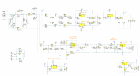
ok - thanks, interesting! / this would not work with the DM unfortunately - see attached.Yes, the DC just flows through half of the internal rectifier. It could work if the internal circuitry needs + voltages only. Practically it feeds the input of the internal voltage regulator(s). It can't work if +/- voltage is needed. You need to check the internal PSU of the DacMagic.
Attachments
Not always 🙂BTW, did you know that if your appliance needs 12VAC from the wall wart, you can equally well use a 12VDC wall wart? Not the way around, though.
Some "Tube" Guitar Pedals use a 12VAC wall wart; from there they get 3 different voltages, go figure:
- 12VAC for 12AX7 filaments
- +15VDC
- -15VDC , both for Op Amps.
*sometimes even a 4th higher voltage for 12X7 plates, thanks to diode-capacitor voltage multipliers.
Which can´t be pulled from a 12V DC supply.
Last edited:
- Home
- Source & Line
- Digital Source
- I must be doing something really dumb?