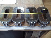
Those ceramic wonders look like industrial microwave oven tubes.
Once you get to the level of 1000s of Watts, an OTL design makes good sense. No expensive risky output xfmr needed. The design could be made modular and fail-safe with plug in modules, with maybe 10 output tubes on each. No need for excessive B+ voltages either.
One could go even further and drive the tubes with one of the new class D IC controller chips. One on each module, and each module using a phase delayed clock versus the other modules. Easy to filter out the HF then, and non interfering with other modules.
Last edited:
again , the only reason to use the tube is for the lower distortion, lower noise floor and lower IMD which means lower feedback levels and better amplification for inductive/reactance audio
OTL needs high level of feedback to stabilize like a typical SS amplifier which negates any benefits from using 'tubes'
OTL needs high level of feedback to stabilize like a typical SS amplifier which negates any benefits from using 'tubes'
Except 4CX1000/1500 are tetrodes. Those will need plenty of N feedback to lower the output impedance anyway.
Using a Circlotron OTL design would give 50% CFB for free.
..
Using a Circlotron OTL design would give 50% CFB for free.
..
Last edited:
OTL needs high level of feedback to stabilize like a typical SS amplifier which negates any benefits from using 'tubes'
Why feedback turns tubes into SS? How? It does not.
All depends on topology. It is absolutely unnecessary to simulate fashionable SS topologies using tubes. It is the same like first SS amplifiers were made of separate 1 transistor common emitter stages, like tube amps. Of course they sounded like a crap!
A Circlotron CFB stage certainly won't need any extra N FDBK around it unless one is going for a big damping factor.
..
..
Last edited:
PRR, have you seen the Bereshkin opt scheme? please comment...
It is very carefully crafted to exactly do what it was made to do: announce football games.
Being a couple *decades* shy of Hi-Fi, it will want major mods for our usual purposes.
thanks PRR, and considering today's Nomex paper availability,
improvements can be done....
i thought the #9 magnet wire used was low frequency. perhaps up to 3khz or less...
if i were to do that today, i will use several strands of #20 wire...
improvements can be done....
i thought the #9 magnet wire used was low frequency. perhaps up to 3khz or less...
if i were to do that today, i will use several strands of #20 wire...
It is very carefully crafted to exactly do what it was made to do: announce football games.
Being a couple *decades* shy of Hi-Fi, it will want major mods for our usual purposes.
Transposing both bifilar wires, one for each primary half, from turn to turn may reduce the unwanted winding capacity by somewhat like the half, compared to straight bifilar winding. But it still remains at some high value. I don't see any benefit at all from winding a conventional, but HiFi PP OT's primary bifilarly. The only exception is Frank McIntosh's/Gordon Gow's Unity Coupling design. But this really doesn't represent a conventional OT 🙂.
Best regards!


Hi Davorin,
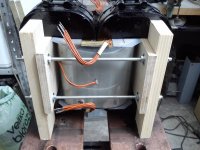
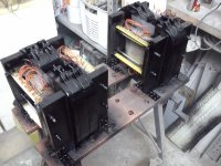
if you would have filled the winding windows almost completely, copper losses significantly were decreased. Was there any reason for you not to do so?
Best regards!
if you would have filled the winding windows almost completely, copper losses significantly were decreased. Was there any reason for you not to do so?
Best regards!
A long thin profile winding has less leakage inductance than a squared up winding cross-section. (due to the leakage paths being nearly as long as the lamination path) This is one reason long E laminations provide superior results. Also toroids with thin windings.
Of course, there is always the question of why not reduce the copper losses further, but unnecessary if a sufficient sized core was chosen to start with.
Of course, there is always the question of why not reduce the copper losses further, but unnecessary if a sufficient sized core was chosen to start with.
Attachments
Last edited:
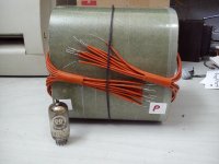
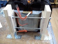
The use of thicker wire would certainly bring fewer copper losses, but I had to use what I had! The wire used (0,40mmCuLak-Grade3) has a high breakthrough strength (more than 7,5kV tested!) and I did not have or could not obtain a thicker wire of equal or similar characteristics.
In this way I got some bigger losses due to higher resistance, but also greater security for possible breakthrough in the primary winding.
Insulation between primary and secondary windings is of a very high quality (teflex), the distance between the ends of the primary windings of the iron core is large (~ 10mm), and the iron core alone does not have contact with angular joints for the fixing on the chassis and will not have any connection with it.
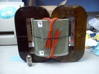
Davorin, what did you use for insulating the midway gap for each primary layer?
Did a primary winding section require layers?
Did a primary winding section require layers?
So approx. 8mm creepage, or were you assuming the strips would act as margin tape and provide effectively a solid insulation barrier?
- Home
- Amplifiers
- Tubes / Valves
- I hope this is the right forum... big amp with output xformers