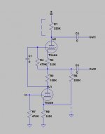
V1B phase splitter ground connection is wrong - Bottom end of R94 should be disconnected from the feedback summing point and then be connected to ground instead.
V1A has no HT connection - Left end of R94 should disconnected from junction of R93 and R92 and then be connected to HT at top end of R89
Amazing to see such errors on a service schematic.
Simon
V1A has no HT connection - Left end of R94 should disconnected from junction of R93 and R92 and then be connected to HT at top end of R89
Amazing to see such errors on a service schematic.
Simon
Last edited:
Regarding Alan's Quiz
Not so fast, might want to study that design a little more closely. The Hons Grubber schematic is not incorrectly drawn, and it is extremely clever. (Note that I had not seen it before today.)
Hint: Take a look at how the plate load resistor of the first stage is bootstrapped by the concertina phase splitter cathode circuit. (You can think of it as a very strange variation on the mu follower with balanced output if that helps..) 😀
Hint: Take a look at how the plate load resistor of the first stage is bootstrapped by the concertina phase splitter cathode circuit. (You can think of it as a very strange variation on the mu follower with balanced output if that helps..) 😀
Bootstrap or not, shouldn't there be at least HV at the plate of the input triode?
Bootstrap or not, shouldn't there be at least HV at the plate of the input triode?
Look at how a mu follower works and the answer will be obvious, then add a plate resistor to the top triode. (There is no direct connection to HV in the lower triode of a mu follower.) Gain in the first stage will be approximately mu.. I'd do a little drawing showing the similarities between the two, but I am at work and can't do one in the time available.
Look at how a mu follower works and the answer will be obvious. (There is no direct connection to HV in the lower triode of a mu follower)
In a mufollower there are two tubes in series.
The lower (voltage gain) tube has somewhat less than halve the power supply HV at it's plate; typical is for instance 350 V power supply - 150 V across upper tube - 50 V across resistor - 150 across lower tube.
I don't see any resemblance with a mufollower.
Sigh, look again, you're being too literal, it's there with some twists. 😀
Bear in mind that the supply is 600V, and the the 220K cathode resistor in the concertina is similar to the additional cathode current boosting resistor in an augmented mu follower. It's not exactly a pure mu-follower but works similarly. (Try ignoring the feedback connections for a moment.)
Attachments
Gee Kevin you're fast.
I redrawn the mufollower myself to see it; there will not be more than some 0.5 mA of current through this stage.
By the way the supply is I guess some 425 V (there is an RC after the 600 V supply with a 450 V electrolytic), and the heater cathode voltage of the "upper" tube (when one tube is used for this circuit) is very near the limit of 200 V.
What is the advantage of this circuit compared to a direct coupled Williamson style one?
OK Kevin, your right! I was thinking it was a convential MI power stage.
Pieter, I just simulated it and it looks OK. The supply is 395V, the top tube cathode is only at about 110V. The top tube runs at 620uA, bottom tube at 128uA. The obvious advantage looks like more gain from just a single twin triode - open loop this input/splitter pair make about 46dB for each output.
Simon
WOW ! I am very surprise about all that !Not so fast, might want to study that design a little more closely. The Hons Grubber schematic is not incorrectly drawn, and it is extremely clever. (Note that I had not seen it before today.)
Hint: Take a look at how the plate load resistor of the first stage is bootstrapped by the concertina phase splitter cathode circuit. (You can think of it as a very strange variation on the mu follower with balanced output if that helps..) 😀
You are perfectly right about this strange "mu-follower" circuit ...
This is what I thought to be the real circuit :
An externally hosted image should be here but it was not working when we last tested it.
But it work very well too, the only differences is much lower gain and a slightly lower distortion ...
I made a Spice simulation with both circuits :
An externally hosted image should be here but it was not working when we last tested it.
The gain with this "conventional" phase splitter circuit is only 22,136 ...
An externally hosted image should be here but it was not working when we last tested it.
The gain with this "mu-follower" circuit is 208,17 ... 9,4 times more ...
A genious Idea or a happy mistake ???
I will remember this one for sure, a very usefull way to get much more gain with exactly the sames tubes and parts ...
My next step will be to make a spice simulation with 6550 tubes, but to get 100W with a 5K load, the Tung-Sol datasheet said they need a -32,5V bias and 65V peak grid to grid or 23V RMS signal, about twice needed to drive the 8417 tubes ... The biggest problem is the output transformer of this amplifier probably have a 4,2K impedance ...
Thank you for your partipation to this small quiz, everybody see where the circuit look strange just like myself but the great winner is Kevin !
Alain.

P.S. I thought there was mistakes on the C.M.I. schematic but I have a doubt, that's why I make this "QUIZ", to get the everybody "bell sound" ... 😀
The 6550 with fixed bias need a maximum 50K grid leak resistors and about 23V signal ... I try the "mu-follower" circuit with a 0,16V RMS input signal and I get :
22,108726 V RMS and 10,63% THD on probe 1 and
23,3158V RMS and 9,96% THD on probe 2 ...
The problem is with 50K grid leak resistors instead of the actuals 100K, there is a lot of clipping at 26,1V peak for the positive amplitude of probe 1 and at - 27,1V peak for the negative amplitude of probe 2 ... Over 20V RMS output, the distortion raise fast so it may be hard to get 100W with an acceptable distortion with this circuit ...
With the "conventionnal" phase splitter, it is much worst ... The wave shape and distortion are very low up to 0,5V RMS input with 50K grid leak resistor but the output signal is only 11,6V RMS ...
I will make a Spice simulation with the complete circuit this weekend !
Alain. 🙂
P.S. I just found out just raising the supply near 450V (the working voltage of the filter capacitor), clipping distortion is lower ...
Last edited:
Thank you for your partipation to this small quiz, everybody see where the circuit look strange just like myself but the great winner is Kevin !
😀
Yes! 3 points for Kevin

The others, me included, just 1 point for taking the effort 😱
It's a pretty clever little circuit, for best performance though it probably is more suited to tubes like the EL34 where grid resistors can be reasonable values.. There is no reason why you couldn't use a higher transconductance triode in place of the upper 12AX7 and get the ability to drive lower load impedances as the benefit. (Grid circuit resistance of 50K in fixed bias with 6550, although to be truthful I have had no problems with 100K with the 6550, but I would not go much higher.)
😀
😀- Status
- Not open for further replies.
- Home
- Amplifiers
- Tubes / Valves
- I have a hard one for you guys