Pat
I know you understand the concept of bridging however in any bridged situation you will never get the power supply voltage capability on the output. Your 36V + 36V will NEVER show up as 72V on the output of the amplifier to the speaker. Very Best case will always be less than 4X the rated output to the speaker in normal mode. I suggest that you don't take my word and do hook up a test setup and this will be the proof.
I know you understand the concept of bridging however in any bridged situation you will never get the power supply voltage capability on the output. Your 36V + 36V will NEVER show up as 72V on the output of the amplifier to the speaker. Very Best case will always be less than 4X the rated output to the speaker in normal mode. I suggest that you don't take my word and do hook up a test setup and this will be the proof.
Those +-37V rails at idle will usually sag to +-33V average when playing loud and this will produce about +-30V output swing when driving a 4 ohm load
But don't expect much more than +-22V swing when driving a 1 ohm load [2 ohm bridged]
Those +-22V from each side produce +-44V over the 2ohm load. Thats 968 W peak and no more than 534 W rms
Belive me, I routinely repair car-audio amplifiers and I have tested lots of repaired ones at full power. I use a custom built 14.4V 72A SMPS and a 1 Farad capacitor as a test power supply
What power supply do you use to provide the 100A peak current required when driving 2 ohms bridge?
The SMPS toroids of car-audio amplifiers are usually wound to show high leakage inductance and to produce controlled supply-rails sagging in order to keep output devices within SOA when driving low impedances
So supply rails sag badly and the typical bridged output power is approximately 3 times the single channel output power instead of the expected 4 times
burnedfingers :
Nice picture. Isn't there something missing? 😀😀😀
Hi, i have done some measurements !!
I have connected the amp to our lab power supply (100amp, 12 volts), and a 2 ohm load wich can take 400w (resistive load), i have added a fan just in case.
I have reached 50volts peak to peak while the power supply was cliping, the protection was set at 60 amp.
The signal started to be cliped on the top of the wave only, telling me that some distortion started too.
So, that gives 50x50/2=1250w ? rms beign 883w.
thats absolutely impossible, but thats it what i have measured. The signal applied was a 1khz sine wave, with a maximum of 3 volts peak to peak output.
2 volts was needed to make the amp clip.
The voltage of the power supply inside the amp, wich is a switching power supply started to drop, from 36 volts to 32v.
It is made of a big toroidal transfo, with very heavy soild coper wiring and very few wounds. There is 8 power mosfets to switch it.
So, by the end, it does realy pump a lot of watts in bridged mode on a 2 ohm load. Thats enough for me to think that it will fulfil my needs to drive two TL with the 2 350w 10 inches clarion subwoofers.
The amp is rated itslef at 250w+250w @4ohm.
The numbers are, i think, realistic. The ratio of the transfo is (36v/12)=3, so the current have to be 3xtime too, 50 volts /2 ohms=25 amps, x3=75 amp, so the amp should draw 75 amp on the 12 line at full power. With all the losses and drop, it should raw maybe less, the power supply was actving its protection set at 60 amp telling me that it is logical.
BTW, the resistor pack was realy hot
Pat Allen
I have connected the amp to our lab power supply (100amp, 12 volts), and a 2 ohm load wich can take 400w (resistive load), i have added a fan just in case.
I have reached 50volts peak to peak while the power supply was cliping, the protection was set at 60 amp.
The signal started to be cliped on the top of the wave only, telling me that some distortion started too.
So, that gives 50x50/2=1250w ?
rms beign 883w.thats absolutely impossible, but thats it what i have measured. The signal applied was a 1khz sine wave, with a maximum of 3 volts peak to peak output.
2 volts was needed to make the amp clip.
The voltage of the power supply inside the amp, wich is a switching power supply started to drop, from 36 volts to 32v.
It is made of a big toroidal transfo, with very heavy soild coper wiring and very few wounds. There is 8 power mosfets to switch it.
So, by the end, it does realy pump a lot of watts in bridged mode on a 2 ohm load. Thats enough for me to think that it will fulfil my needs to drive two TL with the 2 350w 10 inches clarion subwoofers.
The amp is rated itslef at 250w+250w @4ohm.
The numbers are, i think, realistic. The ratio of the transfo is (36v/12)=3, so the current have to be 3xtime too, 50 volts /2 ohms=25 amps, x3=75 amp, so the amp should draw 75 amp on the 12 line at full power. With all the losses and drop, it should raw maybe less, the power supply was actving its protection set at 60 amp telling me that it is logical.
BTW, the resistor pack was realy hot
Pat Allen
burnedfingers said:Pat
I know you understand the concept of bridging however in any bridged situation you will never get the power supply voltage capability on the output. Your 36V + 36V will NEVER show up as 72V on the output of the amplifier to the speaker. Very Best case will always be less than 4X the rated output to the speaker in normal mode. I suggest that you don't take my word and do hook up a test setup and this will be the proof.
Sorry, never meant to be harsh or hard headed. I understand the fact that the power will never go all thru to the speaker because of the disign itslef, i wanted to mean that its the starting numbers.
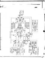
I REALY want to see this schematic !!!
thanks a lot,
Pat Allen
burnedfingers said:You could always build this:
I already have build this...
I plan to use this enclosure for my project, along with the power supply and some more caps that i have.
Pat Allen
Attachments
Quote:
burnedfingers :
Nice picture. Isn't there something missing?
Ok, what is missing other than several additional pairs of outputs, sinks, and emitter resistors. Its a single channel subwoofer amp with crossover on board.
Yes, still trying to send the schematic.
burnedfingers :
Nice picture. Isn't there something missing?
Ok, what is missing other than several additional pairs of outputs, sinks, and emitter resistors. Its a single channel subwoofer amp with crossover on board.
Yes, still trying to send the schematic.
hey pat allen
one of the pros of this schematic is symetry...
I like the idea of symetric amps with current feedback..
if you don't like the op amp, throw it away then with r120 & r133 and give 150k r131 & r132 for high input impedance
and instead of these bloody diodes d105/d105/d107 five a Vbe multiplier with pot to set nice biasing (say 60mA per pair)
Maybe also some power darligtons at output.
results may be nice I think
cheers
burnedfingers said:Quote:
Ok, what is missing other than several additional pairs of outputs, sinks, and emitter resistors. Its a single channel subwoofer amp with crossover on board.
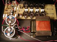
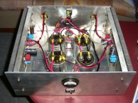
The main heatsink for the output devices is missing
This picture is probably a bad joke since these small stamped-aluminum-sheet heatsinks are rated at more than 15ºK/W and would reach funny temperatures when playing loud in any circuit with rails above +-30V and/or driving loads below 8 ohm, particularly in a closed case with no air flowAlso, there is no thermal tracking between output devices so big current mismatching is guaranteed to occur
NOTE: A transistor mounted on a 15ºK/W heatsink and dissipating 10W will heat up to 15*10=150ºK above the ambient temperature

And I'm not going to ask how did you burnt your fingers... [just kidding but be careful with hot surfaces 🙂]
Eva
Thank you so much for trying to point out the flaws in my design.
Unfortunately you didn't bother to find out the particulars before finding faults.
This picture is probably a bad joke since these small stamped-aluminum-sheet heatsinks are rated at more than 15ºK/W and would reach funny temperatures when playing loud in any circuit with rails above +-30V and/or driving loads below 8 ohm, particularly in a closed case with no air flow.
Well, looking at it from a view not shared by this picture there will be a 105 cfm fan cooling those small heat sinks. The B+ and B- voltage is 65 volts. The later version I built had a sensor on the heatsink to switch the fan from medium speed to high speed.
Funny thing is that it never switched to high speed unless it was being tested.
Also, there is no thermal tracking between output devices so big current mismatching is guaranteed to occur
Well, the amp is debiased on purpose as to not have a problem with thermal runaway of any type. Distortion was still way below .1%
NOTE: A transistor mounted on a 15ºK/W heatsink and dissipating 10W will heat up to 15*10=150ºK above the ambient temperature
Well, one has to account for the type of usage of the amplifier. In its application (subwoofer usage) it normally does not see anything close to what a full range channel would see. In normal operation it doesn't heat up and run hot. I don't consider it a problem then. Only when run into a load at full power does it heat up. With a full set of outputs it is 2 ohm stable.
Now, it is easy to find fault with others work. By the way what have you built that has survived over 14 years? I have over 50 of these in different theatre systems along with custom designed subs and drivers and they are still running without any problems.
I knew someone should say something good about it, because it does sounds respectably good and gives incredible power for what it is.
Defenitively try the biasing with a plain transistor and a pot like the amp of the 80's. I guess it will reduce overall distortion specificaly at low volumes, as one would expect from an amp with poor/low bias.
thanks a lot !
Pat Allen
Defenitively try the biasing with a plain transistor and a pot like the amp of the 80's. I guess it will reduce overall distortion specificaly at low volumes, as one would expect from an amp with poor/low bias.
thanks a lot !
Pat Allen
comment on power figures.
Hi, all. I would like to address the question of power output. I think you are forgetting to derive the r.m.s. value from the rails before doing the math for power.
The rails would be the peak of a sine wave. The formula to derive r.m.s. value is peak voltage X .707. An example:
50 volt rails using this as a.c. value:
50 X 50 = 2500 / 8ohm = 312 watts.
50 volt rails using the formula:
50 X .707 = 35. 35 X 35 = 1225 / 8ohm = 153 watts. Quite a difference! This is why some of the power outputs may seem way exagerated. This also is assuming a perfect world where there are no losses in the amp and the power supply would be regulated rock solid.
In the real world, an amp with 50 volt rails would likely produce about 100 watts into 8ohms.
As for the stamped heat sinks, I have seen an awful lot of commercial amps with this same setup. It must work okay as long as the fan runs.😉 I do not find it "sexy" but it is cheap and functional. Regards, Steve
Quote:
Defenitively try the biasing with a plain transistor and a pot like the amp of the 80's. I guess it will reduce overall distortion specificaly at low volumes, as one would expect from an amp with poor/low bias.
I started that way with a T0-220 all plastic case transistor
mounted on top of a T0-3 metal case output and as one would expect it was very easy to achieve a .003 distortion figure. This however would not deliver the long term life and durability I was after. I figured that sense it was a subwoofer amplifier I could live with a distortion reading of less than .1 but not the .003 I had before. The difference is not audable in a subwoofer amplifier. I was after long term life from a piece of equipment that may likely run 15 hours in a day and I got it.
It might be interesting to note that the amp started as a full range fully complimentary quad diff input amplifier and ended up as a sub amp. Overkill to say the least and still running.
Did you get the schematic I posted?
Pat
After looking at your schematic and your heatsinks...is there a problem of C rise for you also? As mentioned before the 4558 is a dirty Op amp only slightly better than the 1458. I would try a 5532 in its place. A 5532 is a common commercial Op amp that is pretty clean and doesn't suffer from the problem of latching up to the rail like some Op amps do. It might also be a good place to try an OPN. Unless I missed it I didn't see decoupling caps close to the Op amp. You might want to add some small ones.
After looking at your schematic and your heatsinks...is there a problem of C rise for you also? As mentioned before the 4558 is a dirty Op amp only slightly better than the 1458. I would try a 5532 in its place. A 5532 is a common commercial Op amp that is pretty clean and doesn't suffer from the problem of latching up to the rail like some Op amps do. It might also be a good place to try an OPN. Unless I missed it I didn't see decoupling caps close to the Op amp. You might want to add some small ones.
No, i have no problems with overheating at all, this amp runs good during summer.
One thig i may say, they dont suggest to run it in bridged mode with a 2 ohm load, but a 4 ohm one. I do run it at 2 ohm at full volume, i ran very hot and never run out. 😀
There is no caps around the op amp, so i may add few if i redo the pcb.
The amp pictured above is not the amp on the schematic, but it will.
This pictured amp is a Zen amp.
Pat Allen
Re: comment on power figures.
I run it a 2 ohm. Did i say that i run it a 2 ohm?
I run it a 2 ohm.
1225/2=612.5w then.
Pat Allen
gearheaddruid said:
50 volt rails using the formula:
50 X .707 = 35. 35 X 35 = 1225 / 8ohm = 153 watts. Quite a difference! This is why some of the power outputs may seem way exagerated. This also is assuming a perfect world where there are no losses in the amp and the power supply would be regulated rock solid.
In the real world, an amp with 50 volt rails would likely produce about 100 watts into 8ohms.
I run it a 2 ohm. Did i say that i run it a 2 ohm?
I run it a 2 ohm.
1225/2=612.5w then.
Pat Allen
- Status
- Not open for further replies.
- Home
- Amplifiers
- Solid State
- I got this schematic of a power amp, would like comments