there's the problem.
One or more of the mosFETs is hotter than the remainder. Overstress the FETs by fitting too small a heatsink and then running one of them at a higher bias current and your amplifier tells you it does not like what you ask it to do.
Thank you for the guidance Andrew...I have admired your well crafted responses here on the board for a couple years now...
Measure the voltage across each source resistor to confirm the current through each mosfet.
Report back what you have.
If they are too different you will need to match them. I assume you know how to do this.
If not ask, or check out the passdiy site for more info.
Report back what you have.
If they are too different you will need to match them. I assume you know how to do this.
If not ask, or check out the passdiy site for more info.
Amp has been running for 48 hours straight...
LEFT...................RIGHT
IRFP244 515mv IRFP9240 526mv
IRFP244 514mv IRFP9240 522mv
IRFP9240 515mv IRFP244 524mv
IRFP9240 516mv IRFP244 521mv
The right channel is the one with the problems
Both channels are showing a stable <10mvDC
LEFT...................RIGHT
IRFP244 515mv IRFP9240 526mv
IRFP244 514mv IRFP9240 522mv
IRFP9240 515mv IRFP244 524mv
IRFP9240 516mv IRFP244 521mv
The right channel is the one with the problems
Both channels are showing a stable <10mvDC
Looks good to me.
I think your problem was with the way you had implemented the current limiting circuit, it could also be what Nelson said earlier.
Are you by chance using exotic/home brew speaker cables on your other speakers. These could be causing oscillation.
I think I would drop your total dissipation to 80W/ch so you have a bit of margin of safety for the possibility of the bias increasing when you have music running through it.
when I went to hook them up to the CHR70's I checked the dc offset and it was ~150mA. I reduced it to ~0 and fired everything back up. That is when the crackle happened.
as Nelson said, you adjust bias balance to get low dc offset
you cant just adjust for low dc offset
it will change bias setting
your latest measurements looks perfect, and shows a perfect working amp, which gives me a feeling theres something you may be doing wrong, when adjusting
or maybe I havent understood what you are saying
have you tried to reverse channels on your signal/preamp, to make sure thats not the problem
those pair Vrs look very close.Amp has been running for 48 hours straight...
LEFT...................RIGHT
IRFP244 515mv IRFP9240 526mv
IRFP244 514mv IRFP9240 522mv
IRFP9240 515mv IRFP244 524mv
IRFP9240 516mv IRFP244 521mv
The right channel is the one with the problems
Both channels are showing a stable <10mvDC
The worst case is 4mV in 526/522. That indicates <1% error in matching.
I wonder if the tolerance of the resistors is bigger than that 1%? Are they matched as well?
Regular copper speaker wire ~ 14 ga.
I understand the bias process...get to the bias setting then re-check DC offset and adjust. Then re-check bias, and go in half steps on each pot - I only have one DMM at the moment.
The bias resistors are 3W Panasonic 5% - my DMM's lowest ohm scale is 200ohm to 1/10th ohm so I can not match these with my existing DMM.
I think I will let the amp burn in for a while longer and then adjust the bias down to 470mV then give it a try. I am beginning to believe that it may have been too high bias setting coupled with an improper hook up to the current limiting circuitry.
Thanks for all the guidance with this!
Last edited:
using the 199.9mVdc scale or the 1999mVdc scale you can match to better than 0.5% and with care plus good technique you can get down 0.1% matching.The bias resistors are 3W Panasonic 5% - my DMM's lowest ohm scale is 200ohm to 1/10th ohm so I can not match these with my existing DMM.
Oh brother...
Got around to hooking it up to speakers tonight and guess what...the right channel blew another 2sk170 when I cranked it up...ARRRRGHH!
So even with the current limiting in place...it still blows...
It really is starting to look like the mismatch of the right channel mosfets is the culprit.
It may be time to unhook the extra pair and wait out some matched mosfets.
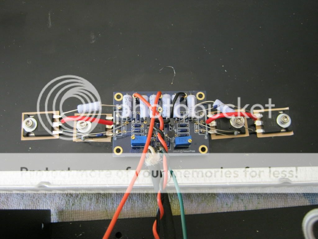
Some of those lead wires look very close to each other.
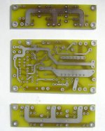
To tidy things up a bit I would use Peter's pcb as a driver board, and buy yourself some prototype board. You want a thin strip for each side of the driver board and mount your mosfets and resistors on that board.
Something like this (see the picture)
To tidy things up a bit I would use Peter's pcb as a driver board, and buy yourself some prototype board. You want a thin strip for each side of the driver board and mount your mosfets and resistors on that board.
Something like this (see the picture)
Attachments
Last edited:
I remember nelson saying that you want to make sure you keep the output and input wires as far away as possible from each other. In the picture they run almost on top of each other. If this is how you have it set up at the moment, route the ouput wire away from the input wire.
Just one more thing. On the left side of the picture you can see a thermistor wire and resistor wire crossing each other (almost touching). When the heatsink is mounted verticaly there is a good chance that the weight of the thermistor could cause it to come into contact with the resistor lead wire.
Just a few things to check out.
Last edited:
When the sink goes back vertical the inputs and outputs are reasonably separated.
The resistor is above the thermistor...pic is deceiving. There is plenty of clearance as the thermistors on both sides sit pretty flat and the additional 47 ohm resistors arc above everything.
The resistor is above the thermistor...pic is deceiving. There is plenty of clearance as the thermistors on both sides sit pretty flat and the additional 47 ohm resistors arc above everything.
- Status
- Not open for further replies.
- Home
- Amplifiers
- Pass Labs
- I fried someting on my F5...ugh