I recently recognized that my CDP-X5000 has a high noise / hiss level.
Even a Philips CD-104 from 1985- playing a silent test track- has an almost unnoticeable noise floor.
Putting the volume of my amp to full level I even hear the tick of the swing arm´s tracking pulse more than any hiss.
I assume the hiss of the X5000 is about -70 to -80dB.
Anyway, besides the fact that a second generation player beats an X-generation player noise-floor-wise:
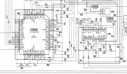
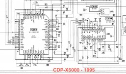
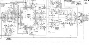
Checking the service manual of the X5000 I recognized that a D/A converter
CXD2562Q feeds the Current Pulse D/A Converter CXA8042.
The CXA8042 is widely spread it can be found in almost any 1-bit player.
The CDP-X5000 is purely CD.
But the same combo of the CXA8042 following a D/A converter can be found with SACD:
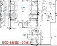
In an SACD-555ES the D/A Converter is a CXD9521 followed by the CXA8042.
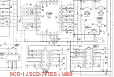
Same with the flagships SCD-1 and SCD-777: Here a CXD8594 is followed by the CXA8042.
The datasheets of the D/A converters are not available.
But as the CXD2562, CXD9521 and CXD8594 are labeled D/A Converters I assume
thar their analog output (labeled L2 and R2) feeds the 1bit-DAC CXA8042 - which means that the signal is converted twice.
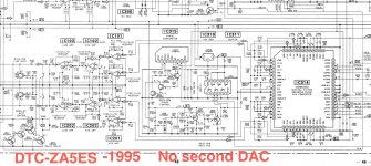
Another hint is the datasheet of a ZA5ES DAT -
okay, it is a DAT but the playback electronics are almost the same as with CD: Here L2 and R2 feed the analogue filter and output stage as usual.
The D/A converter IC is a CXD8505.
So, did I get something wrong? Where is the benefit of converting a signal TWICE, first step delta sigma, second step 1-bit,
Why not putting the signal directly into the analogue output stage?
To please the reviewers and for marketing? Did I miss something?
The schematics of the gear mentioned is attached...
All the best,
Salar
Even a Philips CD-104 from 1985- playing a silent test track- has an almost unnoticeable noise floor.
Putting the volume of my amp to full level I even hear the tick of the swing arm´s tracking pulse more than any hiss.
I assume the hiss of the X5000 is about -70 to -80dB.
Anyway, besides the fact that a second generation player beats an X-generation player noise-floor-wise:
Checking the service manual of the X5000 I recognized that a D/A converter
CXD2562Q feeds the Current Pulse D/A Converter CXA8042.
The CXA8042 is widely spread it can be found in almost any 1-bit player.
The CDP-X5000 is purely CD.
But the same combo of the CXA8042 following a D/A converter can be found with SACD:
In an SACD-555ES the D/A Converter is a CXD9521 followed by the CXA8042.
Same with the flagships SCD-1 and SCD-777: Here a CXD8594 is followed by the CXA8042.
The datasheets of the D/A converters are not available.
But as the CXD2562, CXD9521 and CXD8594 are labeled D/A Converters I assume
thar their analog output (labeled L2 and R2) feeds the 1bit-DAC CXA8042 - which means that the signal is converted twice.
Another hint is the datasheet of a ZA5ES DAT -
okay, it is a DAT but the playback electronics are almost the same as with CD: Here L2 and R2 feed the analogue filter and output stage as usual.
The D/A converter IC is a CXD8505.
So, did I get something wrong? Where is the benefit of converting a signal TWICE, first step delta sigma, second step 1-bit,
Why not putting the signal directly into the analogue output stage?
To please the reviewers and for marketing? Did I miss something?
The schematics of the gear mentioned is attached...
All the best,
Salar
Attachments

They do have inputs but it seems like the pin configurations and descriptions change from chip to chip.
All have a Xin pin which supplies the chip with a master clock.
Then there's the typical LR clock and bit clocks mentioned in places, plus the data lines.
Some chips have two data lines corresponding to 4 DAC channels, L1, L2, R1 and R2. These are balanced and what looks like, current output DACs. The 4 DAC channels are used for deriving a stereo balanced output.
L1+ and L1- are converted and summed into a single ended voltage output, say LH. L2+ and L2- are also converted and summed into a single ended voltage output, call it LC, that's 180 degrees output phase with LH. These are then both used to drive the two lines of a balanced output. The Rs do the same but for the right channel.
If you want the single ended output you can either use LH and RH alone with ground, or you could go so far as to sum LH/LC and RH/RC internally first.
Effectively the DAC chips are 4 channels in one and functionally they operate in a very similar way to how two PCM1792s, from TI, would operate if two were inside one package.
http://www.ti.com/lit/ds/symlink/pcm1792a.pdf
See the output schematics at page 35 and onwards.
Hi Fifth Element,
Thanks a lot to the in depth description of -I assume- the D/A Converters
CXD2562, CXD9521 and CXD8594.
But the question of this thread is a different one.
Why do the schematics show that the current outpiuts of these D/A converters
feed the input of a second DAC - the "Current Pulse" (aka 1-Bit I guess) instead of simply going to the filter / output stage?
This is complete nonsense to me to me as I always thought that 1-bit quantisation follows a decoder or is part of digital filtering -
within the digital realms and and NOT done by simply requantisating
the analog output of a previous DAC - which probably introduces errors...
All the best,
Salar
my guess
I suppose IC603 of your first pic of post#1 is delta sigma modulator and can't output ideal analog signal. Then, the second DAC IC504 converts it to ideal analog signal which feeds to analog LPF.
IC603 has both digital and analog signal, which inevitably has less analog quality. The second DAC is a true analog device with no digital signal, which means IC504 can have better SNR than IC603. DSD signal can be regarded as both digital and analog. The output of IC603 is quasi-analog(almost digital) which is used to drive IC504 that can output true analog DSD.
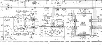
IC314 of your fourth pic is probably a newer DAC which includes both IC603 and IC504 without degradation of SNR. DSD signal feeds to analog LPF must be an ideal analog signal with high SNR. This is practically very difficult to achieve. I have not yet succeeded to make such ideal DSD signal. My current solution for this is similar to SONY approach like two stage DA conversion. This works well.
I suppose IC603 of your first pic of post#1 is delta sigma modulator and can't output ideal analog signal. Then, the second DAC IC504 converts it to ideal analog signal which feeds to analog LPF.
IC603 has both digital and analog signal, which inevitably has less analog quality. The second DAC is a true analog device with no digital signal, which means IC504 can have better SNR than IC603. DSD signal can be regarded as both digital and analog. The output of IC603 is quasi-analog(almost digital) which is used to drive IC504 that can output true analog DSD.
IC314 of your fourth pic is probably a newer DAC which includes both IC603 and IC504 without degradation of SNR. DSD signal feeds to analog LPF must be an ideal analog signal with high SNR. This is practically very difficult to achieve. I have not yet succeeded to make such ideal DSD signal. My current solution for this is similar to SONY approach like two stage DA conversion. This works well.
Hello xx3stksm,
Thanks a lot for your guesses!
IC 314 from the fourth picture is old -
it is located in a DTC-ZA5ES DAT from 1994.
But if a Delta - Sigma signal is not good, (which means that 80% of all DACS and CD-Players are crap) how could the second Dac make it better?
Unfortunately the pictures I posted have no names , so I named them now. They show that the curcuitry did not change over 10 years.
Attachments
I was under the impression that SONY succeeded to make ideal DSD signal which can directly feed analog LPF. But if they couldn't, two-stage DAC like CDP-5000 and SCD-1 was their solution for the problem, and they continued this method for many years. From my experience, this story is more reasonable.
DSM and DSD is not the same concept, though they use delta-sigma topology. DSD is 1-bit stream which can be regarded as both analog and digital. The second DAC of CDP-5000 accepts it as a digital signal to trigger internal current switch. This means no need for high SNR signal because it's digital. The second DAC (IC504)outputs high-quality analog signal to analog LPF. The input of the second DAC is digital DSD, while the output is analog DSD. The first DAC(IC603) probably can't output excellent analog DSD.
DSM DAC usually accepts digital signal and outputs a multi-bit analog signal, not 1-bit resolution.
That's quite odd indeed. You'd figure that they'd combine all the stages required for accurate D/A conversion inside the same chip. DSD looks essentially like a PWM stream. So in a sense the second DAC is a bit like a buffer.
Sony's 1bit DACs are very vulnerable to power supply noise because the supply is also their reference.So separating digital block and analog block was a solution.
The things marked current pulse are I/V conversation stages.
It is not. It does make probably pulse with modulation. Again, all the schematics look like some unnecessary part (the CXA8042 claiming to be a D/A Converter) is inserted between current (probably balanced) output and analog filter and output stage.
Check also this article, where the seller of the analog output stage ZapFilter
has made a tutorial how to bypass the CXA8042:
L C Audio Technology / XA50 Bypass
Here comes another proof that the 1 Bit Dac CXA8042 does not seem to be
necessary:
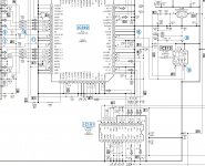
In the beginning of this thread I posted the schematics of a CDP-X5000 where a CXD2562Q D/A converter is combined with the CXA8042 D/A converter. Same combo works in a CDP-XA50ES.
Now the schematics of a CDP-911:
The CXD2562Q - followed by analog filtering and output stage as usual.
So, whats the use - simply marketing?
necessary:
In the beginning of this thread I posted the schematics of a CDP-X5000 where a CXD2562Q D/A converter is combined with the CXA8042 D/A converter. Same combo works in a CDP-XA50ES.
Now the schematics of a CDP-911:
The CXD2562Q - followed by analog filtering and output stage as usual.
So, whats the use - simply marketing?
Attachments
Yeah upon my initial glance over I got it wrong, but it's as has been said by the other folk here.
Due to SACD/DSDs inherent limitations the actual D/A conversion process (at least with Sony's DACs) is susceptible to power supply noise.
Sony get around this issue by having two separate processes. Normally you'd have everything inside one chip, but it would appear that doing so would introduce power supply non-linearities into the second stage that compromise the overall D/A processes performance.
Separating the two allows for physical separation, reducing noise inherent to the ground plane and easily allow for providing a separate, clean, power supply to the second stage.
The X5000 and XA50ES are not DSD at all.
Good old Compact Disc.
Also the supplies for the digital stages are not seperated...
Same 7805 voltage regulator for all DACS...
Good old Compact Disc.
Also the supplies for the digital stages are not seperated...
Same 7805 voltage regulator for all DACS...
If they are from a similar era as some of Sony's SACD players then it's possible that Sony simply recycled the same hardware from one player to the next. SACD players can obviously still play CDs.
It is not. It does make probably pulse with modulation. Again, all the schematics look like some unnecessary part (the CXA8042 claiming to be a D/A Converter) is inserted between current (probably balanced) output and analog filter and output stage.
Check also this article, where the seller of the analog output stage ZapFilter
has made a tutorial how to bypass the CXA8042:
L C Audio Technology / XA50 Bypass
It would be interesting to see what an oscilloscope shows at CXD2562Q pins 16 and 18 (or 21 and 23), with various input signals (and with a “digital silence” signal, which was your initial concern), before you decide to omit the CXA8042
I think there may be some clues in the description of the DAS-R10 on this website.
Sony DAS-R10 on thevintageknob.org
Sony DAS-R10 on thevintageknob.org
If they are from a similar era as some of Sony's SACD players then it's possible that Sony simply recycled the same hardware from one player to the next. SACD players can obviously still play CDs.
SACD was introced in 1999. The X5000 and XA50ES mentioned are from 1995.
It would be interesting to see what an oscilloscope shows at CXD2562Q pins 16 and 18 (or 21 and 23), with various input signals (and with a “digital silence” signal, which was your initial concern), before you decide to omit the CXA8042
Unfortunately I have an old scope that just goes to 15mHz. A am not sure whether it is able to properly display the signal...
I think there may be some clues in the description of the DAS-R10 on this website.
I love vintageknob. It gives us back the feeling when we were young: Flattening our noses on shop windows yearning for the gear wo could not afford.
Now we might afford it but the gear has lost the sexy over engeneering we loved 🙂
But still vintageknob repeats more or less the marketing - rubberish from the catalogues back then -
not very helpful... Same with the DARS-10.
So please gentlemen, no guesses but plain explanation why there is a multibit DAC followed by a 1/bit Dac, probably PWM...?
- Status
- Not open for further replies.
- Home
- Source & Line
- Digital Source
- I do not understand it - did Sony really put two Dacs in series for 1-Bit?