Hey guys.
I have been working on a circuit for my condenser microphone. It's almost finished. I got the pcbs made for it. Just thought I would post it on here to get some feedback from all you smarties. Cause me stupid, but sometimes capable.
Here is the schematic. It's a JFET diff amp that was published by a nifty old feller named Erno Borbley. I needed the input to be JFET because it's being fed by a large diaphragm condenser capsule that has really high impedance. The diff amp couples to a high-performance impedance converter I found in a book called "The Art of Electronics" on page 160. It boasts a THD performance of .001% distortion. From that I got it being converted to a balanced signal using a 1:1 ratio transformer. The transformer is a Lundahl 1570. The guy at Lundahl said I could use it as a mic output, and it would only add 50 ohms to my output impedance. The dual JFETS are LSK389A. The JFETS that are helping it are J310's. The J505 that is sinking current for the diff amp; is sinking 1ma of current. I added a feedback circuit to control the gain. I left off a cap on that circuit that is supposed to cut out the really high frequencies because I noticed that it caused my phase shift to dip down below 20 khz. Because of this, the frequency response goes all the way to 1 mhz. Will that cause problems? i dunno? Maybe someone can shed light on that. By the way, the transformer doesn't appear on the schematic, just use your imagination.
Here is schematic

Here is a pic of the output transformer datasheet

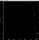
Here is picture of bode plot

In my spice program, the circuit without transformer measures .009% THD. I wanted to go the super linear route for this microphone, because I like the AKG C414 sound, and they make that their design philosophy. I modeled it after the AKG C414 B-ULS.
I have been working on a circuit for my condenser microphone. It's almost finished. I got the pcbs made for it. Just thought I would post it on here to get some feedback from all you smarties. Cause me stupid, but sometimes capable.
Here is the schematic. It's a JFET diff amp that was published by a nifty old feller named Erno Borbley. I needed the input to be JFET because it's being fed by a large diaphragm condenser capsule that has really high impedance. The diff amp couples to a high-performance impedance converter I found in a book called "The Art of Electronics" on page 160. It boasts a THD performance of .001% distortion. From that I got it being converted to a balanced signal using a 1:1 ratio transformer. The transformer is a Lundahl 1570. The guy at Lundahl said I could use it as a mic output, and it would only add 50 ohms to my output impedance. The dual JFETS are LSK389A. The JFETS that are helping it are J310's. The J505 that is sinking current for the diff amp; is sinking 1ma of current. I added a feedback circuit to control the gain. I left off a cap on that circuit that is supposed to cut out the really high frequencies because I noticed that it caused my phase shift to dip down below 20 khz. Because of this, the frequency response goes all the way to 1 mhz. Will that cause problems? i dunno? Maybe someone can shed light on that. By the way, the transformer doesn't appear on the schematic, just use your imagination.
Here is schematic
Here is a pic of the output transformer datasheet
Here is picture of bode plot
In my spice program, the circuit without transformer measures .009% THD. I wanted to go the super linear route for this microphone, because I like the AKG C414 sound, and they make that their design philosophy. I modeled it after the AKG C414 B-ULS.
Last edited:

I thought I would post pics of the mic itself. I was amazed that a large transformer could fit into such a small microphone, but it really can. The mic is a Blue Baby Bottle (which I completely gutted). Here are pics of the new PCBS with the transformer installed.


R3 is in series with the input audio path, and it´s high value adds up to the input noise. A .noise analysis can tell you what components contribute to the total output or input noise.
A tiny bit of leakage in the 1G gate bias resistor ends up as amplified offset to the output, saturating the transformer. Modern input condenser mike input stages have a slow dc loop to compensate the gate bias resistor leakage.
A tiny bit of leakage in the 1G gate bias resistor ends up as amplified offset to the output, saturating the transformer. Modern input condenser mike input stages have a slow dc loop to compensate the gate bias resistor leakage.
Last edited:
Good point about the high impedance of the feedback network. Classical condenser microphone amplifiers just use AC coupling to get rid of offsets.
If you need a -10dB switch/pad best is to lower the bias voltage accordingly, better than a cap in parallel to the capsule. Very high R resistors can have distortion, as their resistance varies with the voltage applied. Bootstrapping is a possible solution. 1G is on the low side for optimal noise. A non differential input stage is better noise wise, as the other branch signal of the diff stage (J2) is not contributing to the output.
Feed the output into an integrator, LP filter the intergrator opamp output and connect it to the footpoint of R6 (1G). disconnect R6 from gnd.
Wow thats neat, I will have to research that. And that would eliminate the 1g resistor from causing dc offset that gets amped? Kinda like a circuit to trim dc offset at the end of an opamp? I think I got it.
When you leave out that extra filter (the noise coming out of the integrator will be negligible anyway), you can design it to have a second-order Butterworth high-pass response. That will be flatter than an ordinary AC coupling will ever be.
I use something similar in an audio power amplifier, see
https://www.diyaudio.com/community/attachments/instellusbuzlus-png.1075671/
I use something similar in an audio power amplifier, see
https://www.diyaudio.com/community/attachments/instellusbuzlus-png.1075671/
Back in 1984 I designed a electret based condenser mike (large sony capsule) using SMT technology (earlier than Sennheiser or AKG) . Back in those days there were no smt pick and place machines in europe. We used a nearby military hybrid manufacturing place to assemble the boards. The mike was introduced on the frankfurt musik messe. The high value bias resistor indeed needed a dc servo loop, to compensate for offsets, as sweat/humidity could influence that. The gain was only 1, but still customers complained about the high signal levels the mike could produce, as many low costs desks did not have much padding capabilities. Your gain of 11 seems a bit high, you just need to overcome the input noise by some margin, otherwise your dynamic range is compromised.
Last edited:
Very interesting stuff guys thanks. I am still pretty new to this. I just started learning and I lean heavily on simulators, so I can focus on topology and don't get bogged down by lots of math. But my understanding is still pretty basic. For instance. I took basreflex's advice and looked at that 10K resistor, and yep it was the largest contributor of noise by far, however, when I change it to a lower value my THD suffers. I was so focused on THD and Phase, I completely didn't even think about noise, I feel kinda dumb. Here is a .noise measurement of just that 10K resistor on the feedback loop.

I am not really sure what to make of this? I am used to seeing noise measurements in decibels. Is 80nVs considered a high noise level for a small signal circuit like this?
I am not really sure what to make of this? I am used to seeing noise measurements in decibels. Is 80nVs considered a high noise level for a small signal circuit like this?
To get realistic results, you have to include the source impedance, that is, the capsule capacitance. You will see that the 1 Gohm resistors dominate at low frequencies then. It's handy to look at input-referred noise.
That signal is nV/rt Hz, you have to integrate that to get a wideband noise signal. If you set the end freq to 20Khz, the simulator can integrate it for you over the band. think it was crtl Right mouse click in ltspice. over the signal name in the plot pane
Ok guys I think I got the spice command right. You're right I had to limit it to 20Khz, which makes sense.
Here is a picture of my input output referenced noise. It's 12uv. This is with R3 at 10K.

I was able to lower this value considerably by changing the feedback voltage divider to 5K and 500 ohms. Like this

This gave a output noise a little above 3uv. Much lower.. see

However, when I do this, it creates a high pass filter at a really high frequency. There is a spike at around 2.3mhz.
Like this picture below. Should I just ignore this since it's so high above the level of human hearing? Need help with that.

Just in case it is a problem, I added a 10pf cap to R4, and it took care of the ugly spike. Made a corner frequency
at about 700khz. Here is a picture of that.


Should I leave this Capacitor off and not worry about the ugly spike? Or should I use the Cap?
Here is a picture of my input output referenced noise. It's 12uv. This is with R3 at 10K.
I was able to lower this value considerably by changing the feedback voltage divider to 5K and 500 ohms. Like this
This gave a output noise a little above 3uv. Much lower.. see
However, when I do this, it creates a high pass filter at a really high frequency. There is a spike at around 2.3mhz.
Like this picture below. Should I just ignore this since it's so high above the level of human hearing? Need help with that.
Just in case it is a problem, I added a 10pf cap to R4, and it took care of the ugly spike. Made a corner frequency
at about 700khz. Here is a picture of that.
Should I leave this Capacitor off and not worry about the ugly spike? Or should I use the Cap?
Attachments
Last edited:
Have you included the capsule capacitance?
We usually call the half-power point or -3.010299... dB point the corner frequency. That's about 3 MHz with the 10 pF included.
What you have to avoid is instability (oscillation). When an amplifier starts to oscillate at some far-ultrasonic frequency, the amplitude of the oscillation normally keeps growing until some stage is driven into hard clipping. This usually causes gross distortion at audio frequencies. It can also cause bias points that seem to make no sense at all, much increased noise and a bunch of other unwanted effects.
Looking at the transfers, I think the circuit is stable with or without 10 pF, but with better damping/more margin with the 10 pF. I would therefore be inclined to include it.
Thank you, sir. This has been really helpful. The capacitance of the capsule is 33pf. I have run simulations with it included in the circuit, but I have hesitated to post it here because I am not sure if I am adding it correctly into Qspice. I know it's just a symbol for a capacitor, but should I add it before, or after the AC voltage source on my schematic? The capsule is grounded on one side, and the AC is technically not going thru one side and out the other, it's kind of originating in the middle of the capacitor (capsule). So here are my two options.
I can put it before the AC sine wave generator like this...

Or should I put it after the AC like this...

When I put it after I get this as my noise figure...

Maybe that is the realistic figure I should expect.. I dunno.
I can put it before the AC sine wave generator like this...
Or should I put it after the AC like this...
When I put it after I get this as my noise figure...
Maybe that is the realistic figure I should expect.. I dunno.
Last edited:
voltage source in series with the cap(sule). now do the math by converting the noise to equivalent dB Spl, what sensitivity is the capsule .the large membrane ones are usually around 10-15mV at 94dBSpl (1pascal/m2)
The second schematic is correct.
By the way, because your ears are not very sensitive at low frequencies, condenser microphone noise is usually measured with A-weighting. That much reduces the effect of the low-frequency noise you get from the 1 Gohm resistors.
By the way, because your ears are not very sensitive at low frequencies, condenser microphone noise is usually measured with A-weighting. That much reduces the effect of the low-frequency noise you get from the 1 Gohm resistors.
Last edited:
Thanks guys. The capsule is not a real c12 style. It is a cheap Chinese copy. I have had two of them and they are about 20-23mv per pascal, and both were 33pf. Just a little info for anyone thinking of buying a capsule from Aliexpress. It was a crude test with a scope but was fairly accurate. The capacitance for this style of capsule is usually about 65pf. I run the test with an imaginary 65pf capsule, and it reduced the noise by 50%. Will probably have to upgrade capsule further down the road.
- Home
- Source & Line
- Analogue Source
- I designed a circuit for a condenser microphone