Hi,
I've got my hands on 3 hy. pex amplifiers and I would like to know if they work
I am using a Meanwell LRS-200-48 for testing, connecting pin (from module) 1 and 3 for -48v, 2 and 4 for +48v.
After that I am a little lost. I know I need to short pin 7 with the psu ground (earth) to power the amplifier, but does not change anything (is it only a second short or do I need to leave it plugged to the grund from the psu?). Pin 7 gives me around 7 volts when not shorted.
Also, I am using hot (pin 11-13) output as positive and cold (pin 12-14) as negative to connect my speakers.
Regarding the source and audio input, I only have an unbalanced source, so I should connect non-inverted pin 9 as audio positive, and where do I connect the signals ground?
As a novice, any help would be very appreciated.
Last edited:
First of all, those modules need a symmetrical supply, ie. +/-48v (with respect to ground). That won't happen with an LRS supply, since (as per the datasheet) "LRS-200 series is a 200W single-output enclosed type power supply".
Regarding your signal source, its ground goes to ground (pin 6), and the amp's inverting input (pin 10) needs to go to ground as well.
Regarding your signal source, its ground goes to ground (pin 6), and the amp's inverting input (pin 10) needs to go to ground as well.
Khron,
Thanks for your reply! To bad the pwoer supply I bought doe not work for these modules!
I bought it specifically for this modules, and I can't return it.
I assume htat without the proper t power supply thre is no way to test these modules work properly, correct?
Any cheap power supply that you would recommend? should i search for "dual voltage" power supplies?
You can buy two of the Meanwell units and wire them in a specific way to obtain a +/- supply. Or get one of the SMPS units on eBay from Connexelectronics. The +/- 45 volt is good supply. There is only one out + and - but you can split that into two and power two UCD180s. You can see how that that is done at Audiophonics - Produits Hi-Fi Audio Electroniques et DIY - Audiophonics (or buy from them.
SMPS300RE +-45V (dual voltage) 300W, 115V Power Supply, Connexelectronic | eBay
SMPS300RE +-45V (dual voltage) 300W, 115V Power Supply, Connexelectronic | eBay
You can buy two of the Meanwell units and wire them in a specific way to obtain a +/- supply. Or get one of the SMPS units on eBay from Connexelectronics. The +/- 45 volt is good supply. There is only one out + and - but you can split that into two and power two UCD180s. You can see how that that is done at Audiophonics - Produits Hi-Fi Audio Electroniques et DIY - Audiophonics (or buy from them.
SMPS300RE +-45V (dual voltage) 300W, 115V Power Supply, Connexelectronic | eBay
Thanks for your reply!
If I buy another Meanwell power supply, which is cheaper than getting a new SMPS, how would I need to wire both power supplies?
Or... would you recommend any other amplifier that I can use with this power supply?
Regards.
Hello mga2009. The modules are a beauty. I bought one from ebay and am having fun experimenting with it. Please take a look at the thread in this Forum which is entitled NCore design refinement. There maybe info therein for you.
I noticed that the connectors which interface with the pins are missing. My ebay seller did not include a connector; which led me to solder wires [carefully] to the pins.
The heat sink of the module is at power ground. Mount it on a lager heat sink which already has the exact and befitting mounting holes for a TO-3 transistor.
I use the bipolar PSU of a "dead" Radio Shack receiver. It is +/-50 Vdc. The power cord of the receiver is connected to a variac which allows me to vary the resultant bipolar PSU to [UcD] from the recommended minimum of +/-20 Vdc to +/-45 Vdc. The three-conductor orange cord in one of my pictures in the aforementioned thread comes from this receiver.
Fuse the power rails. I use small X-Mas light bulbs which blow at ~0.2A.
UcD180LP OEM is a powerful amp and tame.
Thanks Khron for the info on connecting a non-differential input signal source to UcD.
Best
Anton
Hello mga2009. The modules are a beauty. I bought one from ebay and am having fun experimenting with it. Please take a look at the thread in this Forum which is entitled NCore design refinement. There maybe info therein for you.
I noticed that the connectors which interface with the pins are missing. My ebay seller did not include a connector; which led me to solder wires [carefully] to the pins.
The heat sink of the module is at power ground. Mount it on a lager heat sink which already has the exact and befitting mounting holes for a TO-3 transistor.
I use the bipolar PSU of a "dead" Radio Shack receiver. It is +/-50 Vdc. The power cord of the receiver is connected to a variac which allows me to vary the resultant bipolar PSU to [UcD] from the recommended minimum of +/-20 Vdc to +/-45 Vdc. The three-conductor orange cord in one of my pictures in the aforementioned thread comes from this receiver.
Fuse the power rails. I use small X-Mas light bulbs which blow at ~0.2A.
UcD180LP OEM is a powerful amp and tame.
Thanks Khron for the info on connecting a non-differential input signal source to UcD.
Best
Anton
Anton,
Thanks for your reply. I will take a look to the thread you said.
Yes, the connectors were missing, but I bought a connector from ebay but i think it's not the best way. I think I will search for crimping female pins to connecto to the module (already tried molex and atx but both were to big).
By "bipolar" you mean "dual voltage output" power supply?
I only have the meanwell for now, and I am trying to know how to get a second one to get -48v.
Apparently, all I have to do is connect the positive terminal to the ground/earth of the amplifier and the negative terminal to part of the circuit you want to connect negative voltage to. Is this correct? I am afraid I will burn something, because I would get 48v on the ground.
Or should I connect the +48v from the PSU to the PSU's ground (which will be also connected to earth) and then use the negative terminal of the +48v as -48v to connect to the amplifier module.
Also, If I use 2 meanwell 200W to get +48v and -48v does it mean I get 400W and It would work to power 2 amplifier modules?
Hello mga2009. Bipolar PSU is the same as a dual voltage output power supply.
As recommended by the other DIYers, the LRS-200 single output voltage supply is not suitable by itself to power UcD180LP.
Dual voltage is like connecting two 9 Volt batteries in series as follows:
+9Vdc [+ -]_____This center point is ground____[+ -] -9Vdc
Best that you follow the suggestions of the participating DIYers. I prefer using one DUAL VOLTAGE unit; written as +/- 48 Vdc.
Tell us more about what you'll get to properly power UcD; but do not hook up to the amp.
Best
Anton
The idea is, leave the +48v supply as it is, but the one that will supply the "-48v" will need to have its secondary ground disconnected from earth.
Apparently, all I have to do is connect the positive terminal to the ground/earth of the amplifier and the negative terminal to part of the circuit you want to connect negative voltage to. Is this correct? I am afraid I will burn something, because I would get 48v on the ground.
Or should I connect the +48v from the PSU to the PSU's ground (which will be also connected to earth) and then use the negative terminal of the +48v as -48v to connect to the amplifier module.
Also, If I use 2 meanwell 200W to get +48v and -48v does it mean I get 400W and It would work to power 2 amplifier modules?
The idea is, leave the +48v supply as it is, but the one that will supply the "-48v" will need to have its secondary ground disconnected from earth.
Khron, Anton,
Did I understand your instructions correctly?
An externally hosted image should be here but it was not working when we last tested it.
Sorry for the scheme, I am not a professional in that regard.
Last edited:
By "secondary ground" i meant, the ground ("negative") of the output[/] of the second power supply. So disconnect THAT from earth, not the mains earth input from earth.
Inside the power supply, the output (DC) ground is connected to mains earth (for safety mainly, and to some extent, noise concerns).
Inside the power supply, the output (DC) ground is connected to mains earth (for safety mainly, and to some extent, noise concerns).
By "secondary ground" i meant, the ground ("negative") of the output[/] of the second power supply. So disconnect THAT from earth, not the mains earth input from earth.
Inside the power supply, the output (DC) ground is connected to mains earth (for safety mainly, and to some extent, noise concerns).
Khron,
Sorry, but you mean that I need to disassemble the power supply and disconnect the internal connection between the "secondary ground" of the 2nd power supply and it's input from earth?
Or...
You meant this:
An externally hosted image should be here but it was not working when we last tested it.
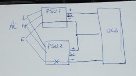
Yes to the first part, but yes-and-no to the drawing.
Here's my version, a bit less spaghetti-like.
But yes, some manual modification is indeed required, in order to adapt non-bespoke subassemblies to fit your needs.
This IS DIYaudio after all, isn't it?
Expect needing to cut some traces (or the groundplane) around the mounting screws on the secondary side of the "negative" PSU.
Switchmode Power Supplies
Linear Power Supply Design
Power Supply Wiring Guidelines
Electrical Safety Requirements
Attachments
Yes to the first part, but yes-and-no to the drawing.
Here's my version, a bit less spaghetti-like.
But yes, some manual modification is indeed required, in order to adapt non-bespoke subassemblies to fit your needs.
This IS DIYaudio after all, isn't it?
Expect needing to cut some traces (or the groundplane) around the mounting screws on the secondary side of the "negative" PSU.
Switchmode Power Supplies
Linear Power Supply Design
Power Supply Wiring Guidelines
Electrical Safety Requirements
Wow, you drawing is much easier to understand.
I will proceed with the disassmbly ob my meanwell PSU to see If I am able to cut the trace between "earth" and "secondary ground". I will probably need help there, so I will upload some pictures.
Also, the "series connection" of + and - between power supplies, it's the "ground" for the UcD and goes to pin 6?
Well, it's a bit of a "standard" of sorts - inputs are on the left, and the "signal" (in this case, power) flows towards the right. Also, positive rails are usually near the top (or "north", if you will), while ground (0v) and negative ones are lower / near the bottom.
And yes, the midpoint between the supplies is (or becomes) the amplifiers' ground.
PS: to ease connections and whatnot, you might want to look into socket headers (or female pin headers). That way, soldering directly to pins is no longer necessary, plus if you change your mind later, it's easy to just unplug them.
If you wanna get even more "fancy", you can design / make (or have made) some small "breakout boards", with socket headers and solder pads (or other connectors) for the power, output and input.
Wow, you drawing is much easier to understand.
I will proceed with the disassmbly ob my meanwell PSU to see If I am able to cut the trace between "earth" and "secondary ground". I will probably need help there, so I will upload some pictures.
Also, the "series connection" of + and - between power supplies, it's the "ground" for the UcD and goes to pin 6?
Thanks for your replies! I will see If i can cut the trace in my PSU, if it is to daunting for me, I will buy a bipolar, dual voltage, symmetrical (all synonyms correct?) PSU... aaaand lesson learned.
Khron, for the connection of the module I bought a 16 pin header, but I find too difficult to solder the wires to the small pins of the header. Maybe I am using a cable too thick (AWG16).
For testing purposes I bought some 2.54 DUPONT FEMALE CRIMPING PINS, I think they will fit properly.
Khron, for the connection of the module I bought a 16 pin header, but I find too difficult to solder the wires to the small pins of the header. Maybe I am using a cable too thick (AWG16).
For testing purposes I bought some 2.54 DUPONT FEMALE CRIMPING PINS, I think they will fit properly.
- Status
- This old topic is closed. If you want to reopen this topic, contact a moderator using the "Report Post" button.
- Home
- Amplifiers
- Class D
- HypeX ucd180lp OEM question