Shouldn't matter as long as it is connected to the ground pins on the nc400.
Then my moduls do not function ! Something is wrong ! Is it possible to destroy anything by faulty connections on the input?
Remember I have done plenty of amps both with balanced and unbalanced design.
Then my moduls do not function ! Something is wrong ! Is it possible to destroy anything by faulty connections on the input?
I don't think we have seen any cases of that - what we have seen is modules being damaged by connecting them to a power supply that has been turned on without any load (so that the capacitors have been charged to a voltage that has been too high).
Remember I have done plenty of amps both with balanced and unbalanced design.
Will try to remember that...
Fixed up all the connections on my amp as well as making sure everything is grounded continuously.
Everything look ok with my wiring connections, specifically the balanced connections?
Everything look ok with my wiring connections, specifically the balanced connections?
red is on pin 2
clear on pin 3
pin 1 is a piece of bare wire that goes from pin 1 to the xlr body tab then to the chassis, the nAMPon wire is part of that connection.
then the bare sheathing goes to chassis.
clear on pin 3
pin 1 is a piece of bare wire that goes from pin 1 to the xlr body tab then to the chassis, the nAMPon wire is part of that connection.
then the bare sheathing goes to chassis.
red is on pin 2
clear on pin 3
pin 1 is a piece of bare wire that goes from pin 1 to the xlr body tab then to the chassis, the nAMPon wire is part of that connection.
then the bare sheathing goes to chassis.
it all looks correct
Thanks. Hopefully tomorrow one of the hypex guys can chime in on my higher then normal DC output.
Thanks. Hopefully tomorrow one of the hypex guys can chime in on my higher then normal DC output.
Do you measure with load ?
When I measure without load I have up to 0,5 V. With load it is 0,7 mv . Maybe you just take to much care !
But I still have no sound. 🙁
Last edited:
I don't think we have seen any cases of that - what we have seen is modules being damaged by connecting them to a power supply that has been turned on without any load (so that the capacitors have been charged to a voltage that has been too high).
Will try to remember that...
Just got an idea ! What happens when the voltage for the output stage is up before the voltage for the inputstage ?
The supply for the input have 2x 4700 uf. followed by 3,3 ohm and then 4 x 4700 uf. So the 2 x 9400 uf. have to be loaded via a little resistor.
IIRC you don't need to provide the input supply voltageJust got an idea ! What happens when the voltage for the output stage is up before the voltage for the inputstage ?
The supply for the input have 2x 4700 uf. followed by 3,3 ohm and then 4 x 4700 uf. So the 2 x 9400 uf. have to be loaded via a little resistor.
If you leave the input supply disconnected it will be provided internally by the nc400
IIRC you don't need to provide the input supply voltage
If you leave the input supply disconnected it will be provided internally by the nc400
I think that is true for the driver stage supply voltage (VDR, pin 11), but not for the op amp supply (+Vsig, pin 6, and -Vsig, pin 12).
I think that is true for the driver stage supply voltage (VDR, pin 11), but not for the op amp supply (+Vsig, pin 6, and -Vsig, pin 12).
As I understand this you work for Hypex ? Is Bruno on vacation or something ?
As I understand this you work for Hypex ?
No, I have been trying to make it very clear that I don't work for Hypex, and have no connection with the company apart from being a happy customer. I am just a fellow hobbyist, just like most of us here.
No, I have been trying to make it very clear that I don't work for Hypex, and have no connection with the company apart from being a happy customer. I am just a fellow hobbyist, just like most of us here.
🙂 You know a lot about those modules .
Next step for me is to ground my cabinet and if that is not enough i have to short circuit those resistors in the supply.
🙂 You know a lot about those modules .
Thanks! But it is mostly from the data sheets and this forum, plus playing around with the modules themselves. It does help that I did study electrical engineering (albeit long ago).
Next step for me is to ground my cabinet and if that is not enough i have to short circuit those resistors in the supply.
Might be an idea to wait a day or two (now that the new working week has begun again) to see if the Hypex guys pitch in with suggestions.
Do you measure with load ?
When I measure without load I have up to 0,5 V. With load it is 0,7 mv . Maybe you just take to much care !
But I still have no sound. 🙁
Mine stays at > 0.5 with speakers connected.
Mine stays at > 0.5 with speakers connected.
Hmm... As you don't have an oscilloscope, could you try measuring the output voltage with the AC range of your multimeter (instead of DC)? It might provide at least some indication of possible HF oscillation going on.
🙂 You know a lot about those modules .
Next step for me is to ground my cabinet and if that is not enough i have to short circuit those resistors in the supply.
Erlend,
Before pulling out the solder iron and inadvertedly destroying your modules, please wait for hypex dudes to respond.
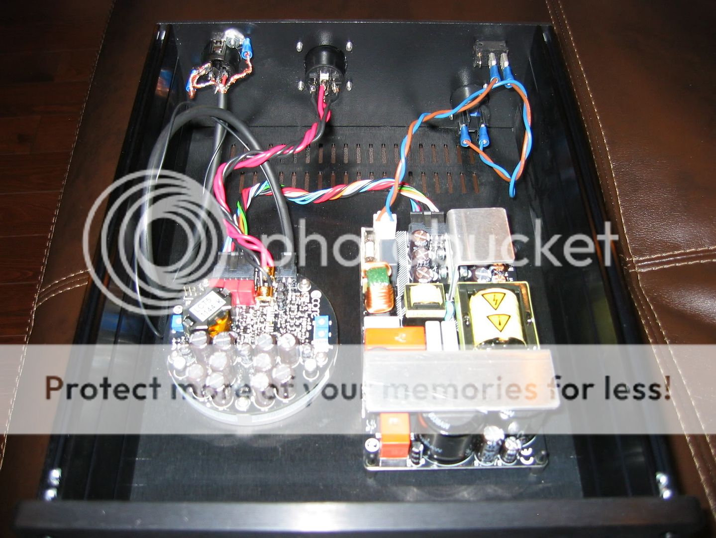
Before that, can you post pictures of your wiring of:
- XLR connectors
- power supply connector
Please describe (preferably in the picture) what voltage goes where on your psu connector.
You stated you have a teeny weeny bit of sound somewhere very deep down, my first idea would be a switch on a ground/+ connection somewhere in the xlr wiring. If that is not the case, maybe the wiring of the psu towards the buffer stage has gone wrong somewhere (depending on the buffer, that could mean no sound at all or a teeny ittle bit of distorted sound).
The fact that your module behaves ~normal (dropping dc offset on speaker connection), or at least, comparable to what other describe, probably means that the output stage is working fine.
- Status
- Not open for further replies.
- Home
- Amplifiers
- Class D
- Hypex Ncore