Ground loop, maybe ?
A loop needs to be closed to be a loop. What path do you suggest the ground loop currents would be taking?
A loop needs to be closed to be a loop. What path do you suggest the ground loop currents would be taking?
If there is also a star ground.
In this case you have 2 connection points between the PSs.
Personally, I prefer to have the grounds of the channels isolated from each other.
Last edited:
There a some assembled stereo or multiple amps featuring dual SMPS600.
Haven't heard of any problems regarding noise / hum though.
Two points don't make up a loop which needs at least two different routes current can take.
Haven't heard of any problems regarding noise / hum though.
Two points don't make up a loop which needs at least two different routes current can take.
If there is also a star ground.
Doesn't really matter in this case.
Yes and no. You have two connection points, but one only goes to the relay coil/optoisolator of the control input, so it is galvanically isolated from the rest of the SMPS1200 circuitry.In this case you have 2 connection points between the PSs.
Sure, we are all free to follow our personal preferences, but in this case there is no rational reason to need the grounds isolated from each other.Personally, I prefer to have the grounds of the channels isolated from each other.
There a some assembled stereo or multiple amps featuring dual SMPS600.
Haven't heard of any problems regarding noise / hum though.
We have to consider also channel cross-talk.
We have to consider also channel cross-talk.
And, in this case, what would cause channel cross-talk?
Remote trigger for SMPS1200
I would suggest this as remote trigger:
The best amp needs the best trigger. 🙂
I would suggest this as remote trigger:
An externally hosted image should be here but it was not working when we last tested it.
The best amp needs the best trigger. 🙂
Last edited:
Same can be used also as power on/off button, in order to avoid the bulky mains switch.
Last edited:
I would suggest this for remote trigger
No need for a double power supply, and no need for double contacts on the relay - and actually no need for the relay. 🙂
No need for a double power supply, and no need for double contacts on the relay - and actually no need for the relay. 🙂
It is needed in order to have the grounds not connected to each other - If you want so. 🙂
It is needed in order to have the grounds not connected to each other - If you want so. 🙂
Yes, if you have a fobia against grounds touching each other, you do indeed need to add a lot of extra circuitry... 🙂
Are you of the opinion that none of the other parts (including the source) should be sharing grounds?
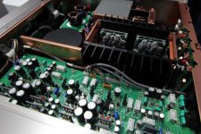
Just had a look at my smps600, it is a combination of a relay in the mains path after the filter and a optocoupler (LTV827). The power for the control circuit is taken directly from the mains path.
Yes, if you have a fobia against grounds touching each other, you do indeed need to add a lot of extra circuitry... 🙂
Are you of the opinion that none of the other parts (including the source) should be sharing grounds?
I want to connect the grounds where I want: at the input, at star-ground or nowhere.
I want to connect the grounds where I want: at the input, at star-ground or nowhere.
Suggested reading: Bruno Putzeys - The G Word.
Just had a look at my smps600, it is a combination of a relay in the mains path after the filter and a optocoupler (LTV827). The power for the control circuit is taken directly from the mains path.
The LTV827 has a forward voltage of 1.4 V, so for a nominal 20 mA current, the 220 ohm series resistor makes sense for 5 V - for 12 V I would add an extra 300 ohm resistor.
I want to connect the grounds where I want: at the input, at star-ground or nowhere.
Could you not use a pair of diodes, each in series of the ground of your trigger circuit to the grounds of the SMPSs, with the anode pointing to the SMPS? It won't be galvanically separated, but there should be no risk for any ground loop. The voltage drop over a diode is only 0.7V IIRC, so no problem reaching the 3.3V min spec.
The LTV827 has a forward voltage of 1.4 V, so for a nominal 20 mA current, the 220 ohm series resistor makes sense for 5 V - for 12 V I would add an extra 300 ohm resistor.
From the SMPS1200 datasheet, regarding SMPS standby:
"Note 1: The current (A) drawn can be calculated as follows: (Vpin – 1.2) / 220"
This formula makes sense for an opto coupler with 1.2V forward voltage connected in series with a 220 Ohm resistor. (It doesn't make sense if it was a connection straight to a relay.)
This formula makes sense for an opto coupler with 1.2V forward voltage connected in series with a 220 Ohm resistor. (It doesn't make sense if it was a connection straight to a relay.)
Exactly. The LTV827 forward voltage is specified as 1.2 V min, 1.4 V typical.
Hi guys. I hope to get a little input to a hard choice reading this whole tread hasn't clarified it 🙂
I'm going for NC400 or NC500 (with standard buffer). These two systems will cost almost the same but of course I would have to assembe the NC400's my self.
My system is MDAC and Dali Euphonia MS5 speakers (4Ohms, 89dB sensitivity).
The advantage with the NC400 is that I can reduce the gain and thereby avoid a U-pad attenutor and slightly better low load performance.
The advantage with the NC500 is higher power at nominal load, higher headroom with bigger PSU and lower distortion at power levels less than 20 watts.
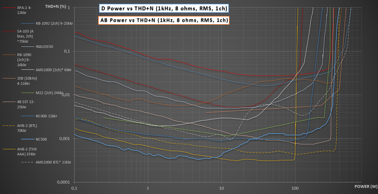
Has anybody heard them side by side? Is the NC500 an improvement in audio quality? I've read some people claiming that but other thinks there is no difference. I guess there should be a little difference since the input buffer designs are different.
The choise is between NC-400 without U-pad attenuator or NC500 with attenuator (but better specs?) What would you guys choose? 🙂
I'm going for NC400 or NC500 (with standard buffer). These two systems will cost almost the same but of course I would have to assembe the NC400's my self.
My system is MDAC and Dali Euphonia MS5 speakers (4Ohms, 89dB sensitivity).
The advantage with the NC400 is that I can reduce the gain and thereby avoid a U-pad attenutor and slightly better low load performance.
The advantage with the NC500 is higher power at nominal load, higher headroom with bigger PSU and lower distortion at power levels less than 20 watts.
Has anybody heard them side by side? Is the NC500 an improvement in audio quality? I've read some people claiming that but other thinks there is no difference. I guess there should be a little difference since the input buffer designs are different.
The choise is between NC-400 without U-pad attenuator or NC500 with attenuator (but better specs?) What would you guys choose? 🙂
Last edited:
- Status
- Not open for further replies.
- Home
- Amplifiers
- Class D
- Hypex Ncore