Mains power.
OK. I guess the built-in soft start in the SMPS makes that a reasonable option.
I would of liked it standby but it would of meant providing a positive signal for the SMPS and additional circuitry. Its really there for interest aesthetics's, The switch is 12A and costs a whopping £16!
I would of liked it standby but it would of meant providing a positive signal for the SMPS and additional circuitry. Its really there for interest aesthetics's, The switch is 12A and costs a whopping £16!
Fair enough! 🙂
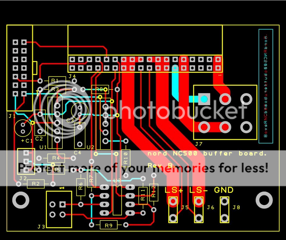
Just logged in an yes working hard but had evening off for the Friday night pub trip. As well as getting 2 pairs of speakers done for the 15th I've promised 4 amps for next week! All bits and PCB's arrived for the input buffer board. My brother will be testing this weekend before sending to me for the real test. Does it sound better?
But sound supreme. Back to Hypex, my brother is building and testing the Input buffer boards today. Rest assured he has a scope and signal generators etc. Hopefully positive news later. Once they are tested etc he will send to me for evaluation.
Back to Hypex, my brother is building and testing the Input buffer boards today. Rest assured he has a scope and signal generators etc. Hopefully positive news later. Once they are tested etc he will send to me for evaluation.
Excellent! Looking forward to the results!
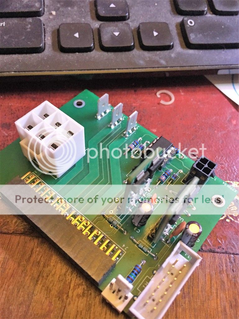
Been one hell of a day! Input buffer board rev B done all working and tested OK
On way back to me for evaluation.
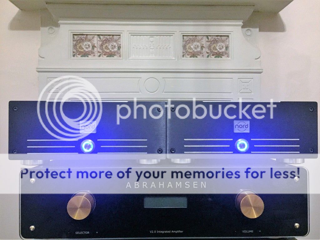
First production Nord Ones made from start to finish for first customer serial no 1001
On test ready for shipment tomorrow. To say I'm knackered but over the moon is an understatement.
On way back to me for evaluation.
First production Nord Ones made from start to finish for first customer serial no 1001
On test ready for shipment tomorrow. To say I'm knackered but over the moon is an understatement.
Been one hell of a day! Input buffer board rev B done all working and tested OK
On way back to me for evaluation.
First production Nord Ones made from start to finish for first customer serial no 1001
On test ready for shipment tomorrow. To say I'm knackered but over the moon is an understatement.
Very cool Boggit!
Been one hell of a day! Input buffer board rev B done all working and tested OK
On way back to me for evaluation.
First production Nord Ones made from start to finish for first customer serial no 1001
On test ready for shipment tomorrow. To say I'm knackered but over the moon is an understatement.
Looking good.
Getting excited too 1001 are going to be mine
Are you all Christmas shopping?
Rev A buffer board arrived back with me, will not have chance to test till weekend, busy building customers amps.
Rev A buffer board arrived back with me, will not have chance to test till weekend, busy building customers amps.
Are you all Christmas shopping?
No, just busy getting ready for a shopping trip to London 🙂
(not really, meeting friends from Singapore that happen to be in London)
hmmm...
Boggit: I do not see .1uF film caps right at the power input pins of the OPA? I would suspect that these are recommended (or low ESR ceramics, etc). Could be Panasonic PPS, or little Wimas...
Are you all Christmas shopping?
Rev A buffer board arrived back with me, will not have chance to test till weekend, busy building customers amps.
Boggit: I do not see .1uF film caps right at the power input pins of the OPA? I would suspect that these are recommended (or low ESR ceramics, etc). Could be Panasonic PPS, or little Wimas...
Its pretty much the Hypex circuit! They must have it wrong! 🙂
I think they have it right for what they are trying to achieve at the price point.
What are caps supposed to be for and what are they supposed to doBoggit: I do not see .1uF film caps right at the power input pins of the OPA? I would suspect that these are recommended (or low ESR ceramics, etc). Could be Panasonic PPS, or little Wimas...
Just spoken to my brother and indeed they are there. They are the brown ceramic disc caps Tantalum next to the Hypex Voltage regulators. They are there to decouple the power rails and to stop high frequency oscillations.
OK
So those caps are on the output of the regs? Typically, for decoupling an opamp, the best approach is to put the final decoupling caps right at the input pins of the opamp itself with as short a trace as possible. I am no EE myself, but this is pretty much standard practice, and I expect that the data sheet of the LM Opamps will state this in their implementation notes. I guess if you measure it all in circuit and find no oscillations then there is no problem, but I would be a little surprised if the Hypex board does not have decoupling caps of around .1 uF (either ceramic or film) right at the input pins of the opamps?
Just spoken to my brother and indeed they are there. They are the brown ceramic disc caps Tantalum next to the Hypex Voltage regulators. They are there to decouple the power rails and to stop high frequency oscillations.
So those caps are on the output of the regs? Typically, for decoupling an opamp, the best approach is to put the final decoupling caps right at the input pins of the opamp itself with as short a trace as possible. I am no EE myself, but this is pretty much standard practice, and I expect that the data sheet of the LM Opamps will state this in their implementation notes. I guess if you measure it all in circuit and find no oscillations then there is no problem, but I would be a little surprised if the Hypex board does not have decoupling caps of around .1 uF (either ceramic or film) right at the input pins of the opamps?
So those caps are on the output of the regs? Typically, for decoupling an opamp, the best approach is to put the final decoupling caps right at the input pins of the opamp itself with as short a trace as possible. I am no EE myself, but this is pretty much standard practice, and I expect that the data sheet of the LM Opamps will state this in their implementation notes. I guess if you measure it all in circuit and find no oscillations then there is no problem, but I would be a little surprised if the Hypex board does not have decoupling caps of around .1 uF (either ceramic or film) right at the input pins of the opamps?
Luckily we, and Hypex are! Hypex provided the schematic, layout and bill of materials to fast track our design. The LM4562 is very tolerant in this respect we have taken this into account in our design with the decoupling capacitors. Even this is over the top in terms of design and production. We want to make a board that is highly flexible in terms of Op Amp change and there individual requirements.
That drives me insane when she does that, soon gets a firm ticking off! Dr Dre would not be allowed through the threshold so a non issue!
Here is the board in action complete with glowing Hypex Voltage Regs and Sparkos Labs Op Amps. Given the performance of the Op Amp I'm going to try there Voltage regulators also.
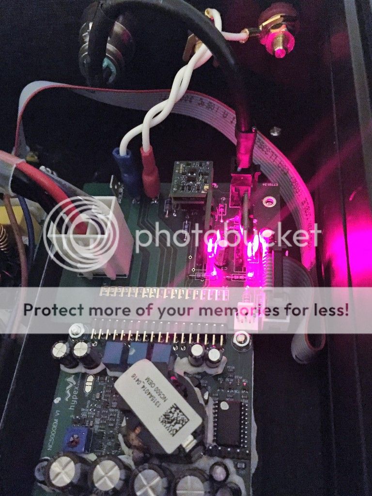
Here is the board in action complete with glowing Hypex Voltage Regs and Sparkos Labs Op Amps. Given the performance of the Op Amp I'm going to try there Voltage regulators also.
Last edited:
- Home
- Vendor's Bazaar
- Hypex NCore NC500 build