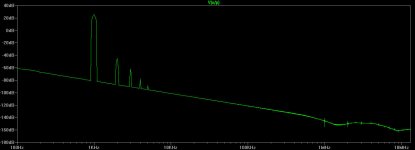
Interesting. Harmonics 4, 8, 12 are very low.
Today in the evening I will measure my new single-ended hybrid front-end with all the voltage gain provided by tubes (2 x 12AU7). We'll see 🙂
Today in the evening I will measure my new single-ended hybrid front-end with all the voltage gain provided by tubes (2 x 12AU7). We'll see 🙂
Fascinating hybrid..... Essentially a Self amp with no VAS, a cathode follower, but in fact 0.55% is not too high BUT the profile is more like SS than tube since the H5 and higher odds are a bit too high.
Valery you have very low loop gain since the VAS is replaced with a cathode follow.
If you use direct coupled SS concepts, I suggest trying a simple, Lin amp - some of simpler Carlos' amp - then plumb a tube into the feedback chain.
I've done this (15 years ago!) and it sounded very, very good........ and there was a dominant tube profile over the SS output.
Hugh
Hello All,
Here is my experiment >Single-ended tube hybrid<
Rather positive, now going to work on PSRR increase 😉
Cheers,
Valery
Here is my experiment >Single-ended tube hybrid<
Rather positive, now going to work on PSRR increase 😉
Cheers,
Valery
Here's my latest attempt.
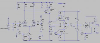
As suggested by Mr.zaichenko, one of the key to a good profile is running the OPS at class A.. However, with it comes the usual problem: heat dissipation, especially if i want to keep the output power target. I tried fiddling around to see if we can get Class A even at high power output with reasonable Power dissipation (Pdiss). Attached schematic is what i have so far..
The output transistors are idling at around 10Watt Pdiss with 2.5A flowing continuously, much lower than the typical Class A Pdiss. I wanted to use the ever-popular LM3886 at first but sadly i failed to simulate it. This would be a crazy looking amplifier! BJTs, Tubes and Chipamps in one case! Sadly (or fortunately?) THD is too low at around 0.03%.. there goes the "tube sound". Only problem is the additional bipolar 5V power supply.. Perhaps Ebay buck converters can solve this problem cheaply?
Attachments
Member
Joined 2009
Paid Member
Tubes doesn't mean high distortion is inevitable or necessarily desirable. I've read reports that people can make tube amps that are so clean they don't have any sound by themselves at all. The trouble with distortion is that it can sound good for awhile but once you go back to a cleaner amp you rather like the cleaner amp more. And distortion makes the sound muddy when you crank up the volume or listen to complex music. So I wouldn't feel bad about 0.03%, especially as you are using feedback.
You could simplify the design, if you want to ?
Not sure why you want D3?
Remove C8 and you'll drop the open loop gain but have more local VAS degeneration ?
What is the power dissipation of Q6, first look at it and I worry a lot, I think R3 & R5 need to be much larger ?
Forget the opamp, it brings nothing to what is already a nice amplifer ?
Perhaps connect R12 to ground instead of B+ would help with wasted heat ?
Just some quick thoughts...
On the contrary, the opamp is the only reason why i can run Class A at high power!
The opamp is critical if i want to avoid having huge chunk of metal just to dissipate the heat of the output transistors. Without it, each transistor would dissipate about 80 Watts which translates to heatsinks the size of a mini-refrigerator.
D3 was my (futile) attempt to add more H2, it just reduces the THD even more!
Q6 dissipates about 1 Watt. I currently use small heatsink and it's running fine.
R12 was connected that way on the PCB i used. I made the original hybrid using readily available PCB. I simply changed the LTP to tubes and some other mods. R12 dissipates minor heat compared to the other component.
Member
Joined 2009
Paid Member
ah... Perhaps I don't understand what you're doing with the chip. It seems you are using it as the power supply for the output devices, a kind of rail-tracker ?
Edit: Is it functionally, any different from simply having a Class AB bias for the output stage using V6 (with no opamp) ?
Edit: Is it functionally, any different from simply having a Class AB bias for the output stage using V6 (with no opamp) ?
Last edited:
Yes, it's a rail-tracker. It keeps the output device's supply voltage constantly 5 volts above the output signal, keeping them from sticking to the rail and still running in Class A. The opamp itself doesn't contribute to the sound.
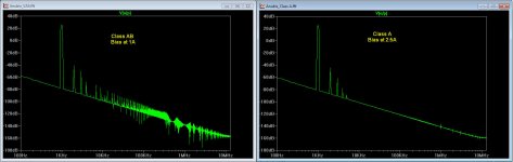
It's different from running a Class AB bias. What's the difference? It's simply the difference between Class A and Class AB. Attached is the difference in harmonic profile. Same input signal, same amount of feedback, same loop gain. Whether the difference is audible, that's another issue 🙂 Do you think it's audible?
edit: THD at Class AB is 0.048%
Attachments
Last edited:
Very cool idea. But I'm not sure why you're saying that the opamp doesn't contribute to the sound ...
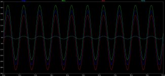
The way i see it, it's the same thing as supplying the output device with constant +/-33V and biasing at 2.5A, only with much less heatsink requirement. The op-amp merely ensures the supply voltages "envelope" the output signal. You can see this enveloping simulation on post #24, last image. Did i miss something?But I'm not sure why you're saying that the opamp doesn't contribute to the sound ...
i guess its just a matter of perspective - as it looks to me that the results will also depend on how well the opamp produces an 23x amplified copy of the input signal. Still like the approach though 🙂
Member
Joined 2009
Paid Member
Hi Bigun,
Yeah i did. It's currently my main amp while i'm finishing my 6BQ6GT tube amp.
As-built schematic is on this thread here: http://www.diyaudio.com/forums/soli...ransistor-hybrid-amplifier-4.html#post3997267
Yeah i did. It's currently my main amp while i'm finishing my 6BQ6GT tube amp.
As-built schematic is on this thread here: http://www.diyaudio.com/forums/soli...ransistor-hybrid-amplifier-4.html#post3997267
Last edited:
Member
Joined 2009
Paid Member
- Status
- Not open for further replies.
- Home
- Amplifiers
- Solid State
- Hybrid Tube-BJT Lin Topology - Tweak Plans