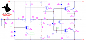
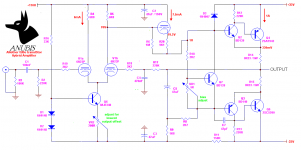
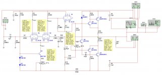
I'm currently listening to a hybrid lin topology having schematic as attached. It actually sounds nice. However, i'm sure something can be done to improve it.. I've gathered some ideas and laid them as points below.. Can anyone comment whether they're worth doing (improvement is audible) and especially why? Also, don't hesitate to add more tweak suggestions. A minor goal would be to increase the second harmonic distortion. I have to add that i'm currently running it in Class A with 1A bias for each output transistors. I will revert back to 50-100mA for Class AB if deemed necessary.
1. Reduce VAS bias current
Currently VAS bias is around 11mA. Personal observation tells me it's usually lower at around 6-8mA.
2. Replace VAS transistor with BF470
Video amplifier transistor with low Cob and high fT. Right now, that MJE350 is dissipating around 1W and has smallish heatsink attached. Spec sheet for BF470 says max Pdiss is 1.8W (Tmb ≤ 114 °C).
3. Remove C4 and C7
Seeing that i already have Miller compensation as grid stoppers (cutoff at approx 1.5MHz, rough guess), would removing these caps sacrifice the stability?
4. Tweak the bootstrap resistor ratio (R8, R9)
My plan is to replace these resistors with a 5K trimpot, connect the wiper tap to C5, inject 1kHz sinusoidal signal to the input and play with the ratio by ear. Not sure if i can hear any difference but i'm hoping to find that sweet spot where 2nd Harmonic would be more dominant. This would also reduce VAS current to around 33V/5K = 6.6mA.
5. Follow the HPF input ≥ 2x HPF NegFB ≥ 2x HPF Bootstrap rule.
I found this rule while browsing and would like to know the reason behind it. There are three high pass filters involved, they are:
- HPF Input is formed by C1 and R2. Currently has cutoff freq of 7.2 Hz
- HPF NegFB is formed by C6 and R17, currently at 0.3 Hz
- HPF Boostrap is formed by C5 and R8//R9, currently at 4.7 Hz
Clearly i'm not following the rule. Changing C6 to 4.7uF changes HPF NegFB to 3.4 Hz and changing C5 to 220uF changes the HPF Bootstrap to 1Hz, adhering to the rule
6. Change the VAS to unity gain stage and reduce the GNFB (or totally remove it)
The idea is to make the valves have more role in the sound. Removing bootstrap capacitor C5, would turn Q1 into unity gain stage (since Rc~Re). This means gain would only come from the valves.
I prefer to keep the basic circuit, i.e not going for something like CCS for VAS, Darlington/MOSFET outputs or something similar. Again, more tweak ideas are very welcomed. I realize all of the tweaks' impact can be simulated in LTSpice.. sadly i am not yet capable to do it.
Attachments
Member
Joined 2009
Paid Member
If you want, you could also try using a tube VAS ?
see post 5: http://www.diyaudio.com/forums/solid-state/194268-dx-hybrid-amplifier-will-produced-soon.html
Also, you could try a low voltage on the tubes, i.e. use the same power supply for output stage and input stage. The 6N23P can operate at some fairly low voltages. It may not be an improvement in the sound, but it would be interesting to try it.
Last edited:
Thank you but adding the Taylor follower changes the basic circuit, something i prefer to avoid. It's not something that can be done in a Friday night 🙂If you want, you could also try using a tube VAS ?
What is the idea behind this? Run the tube at less linear region and increase the THD? I actually did this on a simpler design previously. 6N23P common cathode --> BC547 Emitter Follower --> IRFP250 Source Follower, all DC coupled. It sounds nice at around 45 volts.Also, you could try a low voltage on the tubes, i.e. use the same power supply for output stage and input stage. The 6N23P can operate at some fairly low voltages.
Anyone? Weekend's here.. figured i could use the chance to tweak this hybrid or carry on with the next project.
Member
Joined 2009
Paid Member
Well you wanted to get the tube sound more into the amp so why give up so quickly ?
Why not try unbalancing the LTP to reduce the 2nd harmonic cancellation ?
Also look up on the internet the MUGEN (hibridni pojacavac) amplifier - I have a pdf article but it's nearly 2MB and too large for the forum rules to post it.
Why not try unbalancing the LTP to reduce the 2nd harmonic cancellation ?
Also look up on the internet the MUGEN (hibridni pojacavac) amplifier - I have a pdf article but it's nearly 2MB and too large for the forum rules to post it.
Thanks a lot for that MUGEN amp info, something more to read about hybrid amps.
Very good input about unbalancing the LTP, it's something very easy to do.
You've been the only one to reply, I guess not much interest in hybrid amp here in SS forum 🙂
Definitely not giving up on this tweak plans. Meanwhile, i'm going to learn LT Spice. Hopefully i can get most of the answers to my questions.
Hi Ballpencil, I am also very interested in hybrids - running a parallel project >HERE<, watching your thread regularly 🙄
With regards to tweaking for "more tube sound" - I would try a tube VAS, so that all the voltage gain is done by tubes. Well, it's actually not "tweaking" then - requires some re-design...
I'm trying to move in this direction in >THIS PROJECT< Why don't you like the MOSFET output, by the way?
I'm also trying to reduce the global NFB loop gain (or even remove it), but for that purpose you need some very good (low distortion) power section (class A or error correction sort of topology)...
As a small tweak - I would use Zener instead of R5 for tighter binding the right triode's anode to the rail, maintaining the same voltage as for the left one at the same time - see example, D5 (D6) >HERE<
Hope, it gives some ideas 😉
Keep it up!
Cheers,
Valery
Hi vzaichenko
Mine would be more along the lines of :
- Keep the bootstrap resistors and Vbe multiplier
- Replace the MJE350 VAS with auto-bias cathode follower
- Shift the feed to the non-inverting tube
- Reduce GNFB as necessary
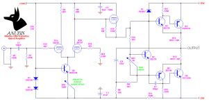
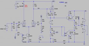
This way, gain would all be coming from the LTP. I haven't looked more into this, especially if i can keep the power supply (+110, +33 and -33V). See the attachment. I like this idea though it might take longer time to do the mod.
You mentioned about needing a low distortion OPS to reduce GNFB, i am already running the OPS at class A. I hope this is good enough!
Not really liking MOSFET as i find they are more electronically fragile (personal experience, or lack thereof) and expensive. I'm not sure if i can hear any difference between MOSFET and BJT inside this gobs of GNFB, so this is not in my to-do list for now.
What is the benefit for this? Same impact with unbalancing the LTP for more 2nd harmonic?
Since my plan was to reduce the GNFB, i don't think another gain stage would be good although it's tube. I don't want to end up with too much gain. Along the lines with the idea stated in #6 (change VAS to unity gain), i had an idea to change it to a tube cathode follower with the condition that i can keep the DC coupling throughout the circuit. Interestingly, that MUGEN amp did just that, with the exception of AC coupling to the OPS.With regards to tweaking for "more tube sound" - I would try a tube VAS, so that all the voltage gain is done by tubes.
Mine would be more along the lines of :
- Keep the bootstrap resistors and Vbe multiplier
- Replace the MJE350 VAS with auto-bias cathode follower
- Shift the feed to the non-inverting tube
- Reduce GNFB as necessary
This way, gain would all be coming from the LTP. I haven't looked more into this, especially if i can keep the power supply (+110, +33 and -33V). See the attachment. I like this idea though it might take longer time to do the mod.
You mentioned about needing a low distortion OPS to reduce GNFB, i am already running the OPS at class A. I hope this is good enough!
Not really liking MOSFET as i find they are more electronically fragile (personal experience, or lack thereof) and expensive. I'm not sure if i can hear any difference between MOSFET and BJT inside this gobs of GNFB, so this is not in my to-do list for now.
I would use Zener instead of R5 for tighter binding the right triode's anode to the rail, maintaining the same voltage as for the left one at the same time
What is the benefit for this? Same impact with unbalancing the LTP for more 2nd harmonic?
Attachments
Member
Joined 2009
Paid Member
This looks good, I like this version. This is a hybrid design I'd have been pleased to put my name to.
You have a coupled-cathode input stage, then a cathode follower buffer with SS output stage.
Unbalancing the LTP allows more tubesound but with the removal of gnfb this isn't worth doing.
What about dc-offset stability - why not use the LTP feedback node - take a signal from the output and feed through an RCR filter to remove the signal but leave the dc intact and feed it to the LTP so as to create a dc-only feedback path ? EDIT: ah, can't work without signal inversion
Last edited:
This looks good, I like this version.
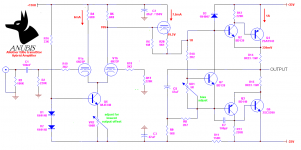
Looks good but it won't work 😛
Just made some verification on voltages around the cathode follower and it didn't add up. Attached is the revised one.
ah, can't work without signal inversion
Why not? Output signal is still in-phase with the input, V1b is still the feedback valve. If somehow there is lack of voltage across R5, output offset will be positive but this means feedback DC to V1b grid will also be positive, increasing V1b's conduction and in turn increase the voltage across R5, pushing the offset back to zero. Did i miss something?
Attachments
Member
Joined 2009
Paid Member
Yes, it will work, as the signal comes off the 2nd LTP device not the 1st. I think it provides a neat way to keep the dc offset under control - what do you think ?
It works
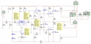
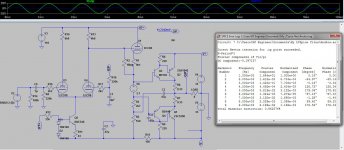
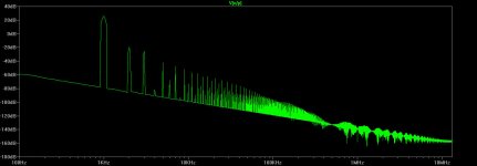
I have simulated this one.
I don't have good models for 6N23P and Toshiba outputs, so I used 12AX7 (slightly lower gain) and NJW3281/1302 (possible option) instead.
It works, although it shows rather high THD, mostly coming from the tube - definitely giving more tube sound 😉
Best value for C2 - 47pF.
Cheers,
Valery
Attachments
That is good idea! Changed the circuit to your suggestion as attached.I think it provides a neat way to keep the dc offset under control - what do you think ?
Thanks a lot vzaichenko. Funny you can get 7mA from a 12AX7 at this voltage, but it's simulation. Harmonic distribution could do with some improvement though. I noticed you use 12AU7 in your own hybrid. 6N23P is closer to that than 12AX7. Even better if you have ECC88 or 6DJ8 as they say these are the direct equivalent.
Would you mind sharing the .asc file or whatever file is related to your simulation? I want to learn LTSpice.
Attachments
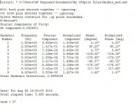
With 6DJ8 it works better
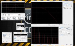
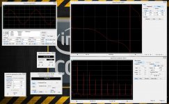
By some reason, in my model of 6DJ8, only the right side works. OK, for simulation I use right sides only. It shows better performance - higher gain (close to 19db, but still lower than "standard" 29db) and lower harmonics (around 0.5% @ 1 KHz, 20W @ 8 ohm output). Note a much better phase response. I have increased both input decoupling and NFB grounding (especially this one) caps, otherwise the lower end of frequency response started decreasing at around 100 Hz.
I'm one of the "white crows" here, using Multisim for simulation 🙂 I learn how to use LTSpice properly, but my abilities there and speed of preparations are much lower, than in Multisim I'm pretty familiar with 🙄
I have attached the file just in case 😉
I have played with some parameters (LTP's and cathode follower's quiescent current combinations), but yours seem to be optimal.
Cheers,
Valery
P.S. Don't pay attention to R4 = 2.2M, that was another "test" I forgot to change back. 1M is good. Or leave it this way ))
Attachments
Last edited:
Member
Joined 2009
Paid Member
Yup, this looks good 🙂
With tubes you have to think about warm-up, how does the circuit behave when the power is applied ?
p.s. I also consider the 6N23P to be the equivalent to the 6DJ8 so this model is more appropriate than the 12AX7.
With tubes you have to think about warm-up, how does the circuit behave when the power is applied ?
p.s. I also consider the 6N23P to be the equivalent to the 6DJ8 so this model is more appropriate than the 12AX7.
Yup, this looks good 🙂
With tubes you have to think about warm-up, how does the circuit behave when the power is applied ?
p.s. I also consider the 6N23P to be the equivalent to the 6DJ8 so this model is more appropriate than the 12AX7.
Yes Gareth, I knew that, just was a bit "destructed" initially with the fact the left half of the model did not work 🙂
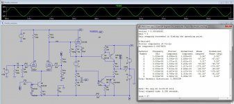
Successfully simulated on LTSpice!
I cheated a bit though.. I took bigun's .asc file for DX-Hybrid and alter it.
Somehow i got 0.88% THD.. 😕
It's 4AM now and i have to work in a few hours so i'll fiddle with this later.
Anyway, .asc file attached. Rename .txt to .asc before loading to LTSpice.
Included also Ayumi model of ECC88 that's posted on the valve forum.
Attachments

Member
Joined 2009
Paid Member
You don't need to post the simulation file as a .txt any longer
http://www.diyaudio.com/forums/forum-problems/199792-its-time-allow-asc-fils-posted.html
Distortion does seem a bit high - you need to play with it a bit more and finesse things if you want good results without feedback and also at higher powers. The choice of tube might be an issue at these voltages/operating points, you have less than 50V across your cathode follower don't you ?? Would a 6N23P perform better in that spot. Look at the distortion before the output stage - how much is from the tube stage (probably quite a bit).
Last edited:
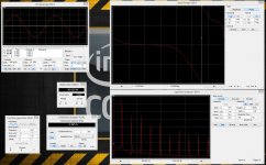
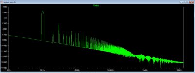
Changed the LTP to 12AX7 and raised the HT+ to 250V for more gain..
I introduced a little feedback and managed to get 0.3% THD with 26dB of gain.. If i bypass the feedback resistor, i get around 0.5%. I'm still not fond of the harmonic distribution though.
How do you reduce odd and increase even harmonics?
Also, i tried to change the cathode follower load bootstrap resistor ratio. Right now it's 1k8 and 1k8 and the simulation runs quickly. However, when i changed to 2k8 and 0.8k, the simulation somehow ran very slowly to a point i had to put it to halt. Why is this?
Attachments
- Status
- Not open for further replies.
- Home
- Amplifiers
- Solid State
- Hybrid Tube-BJT Lin Topology - Tweak Plans