
Indra1, have you built it? Why do you prefer Susan’s topology? Have you noticed those expensive Sowter transformers?
Vgsth variance would be < 500mV, no problem for cap output.There is part variability in the MOSFETs. A pot is necessary at least to start and then can replace with resistors.
Are you sure? I know of no relay that works driven with < 2mA.I added a Power Up Delay
No Sowter, we have local transformer winder here. The topology is simple very low quiescent to maintain Class A operation, and single supplyHave you noticed those expensive Sowter transformers?
Lineup-
My first approach almost twenty years ago, to a "hybrid" design is very much in the spirit of your thread here. I used an IRF510 mosfet, with an LM338 current source, and the 6111WA subminiature dual triode. 36 volts supply to the mosfet, and a voltage quadrupled supply to the 6111 gain stage. It sounded heavenly on my setup, and it made me feel like a rich man compared to other amplifiers I'd tried up until that point.
The nostalgia is hitting me hard, I may have to build another to remember my roots here soon. 🤔
I make it more current to the Relay.Are you sure? I know of no relay that works driven with < 2mA
How much mA should I go for?
I am glad to hear somebody else have had same idea.My first approach almost twenty years ago, to a "hybrid" design is very much in the spirit of your thread here. I used an IRF510 mosfet, with an LM338 current source, and the 6111WA subminiature dual triode. 36 volts supply to the mosfet, and a voltage quadrupled supply to the 6111 gain stage. It sounded heavenly on my setup, and it made me feel like a rich man compared to other amplifiers I'd tried up until that point.
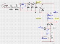
Here is the variable Regulated Power Supply I woulld use for the ECC99. Set on 242VDC.
There is a thread for it: https://www.diyaudio.com/community/...iable-regulator-for-tubes.394757/post-7242208
There is a thread for it: https://www.diyaudio.com/community/...iable-regulator-for-tubes.394757/post-7242208
Attachments
Well, you are the designer, please designate part number of chosen relay, I only know that rev2 delay won't work with any relay that I have ever used.How much mA should I go for?
I set it now for a 5mA relay.
Unfortunately I do not have very good relays in my SPICE.
The one I use is a virtual relay. Where I can set the on current level. Also off current.
I have now designed for ON 5mA and OFF 0.5 mA.
Hope it is good enough 🙂
Unfortunately I do not have very good relays in my SPICE.
The one I use is a virtual relay. Where I can set the on current level. Also off current.
I have now designed for ON 5mA and OFF 0.5 mA.
Hope it is good enough 🙂
The virtual relay has the following data by default:
Inductance: 1 mH
Resistance: 1 Ohm
On Current: 50 mA
Off Current: 25 mA
Inductance: 1 mH
Resistance: 1 Ohm
On Current: 50 mA
Off Current: 25 mA
Revision 3
I changed the relay. Now it has ON current 50 mA. Approximate 8 seconds of delay.
Also added Zobel filter on the output.
Also added one resistor to charge the big output capacitor. It is in fact 10000uF.
Some cosmetic changes, too.
I changed the relay. Now it has ON current 50 mA. Approximate 8 seconds of delay.
Also added Zobel filter on the output.
Also added one resistor to charge the big output capacitor. It is in fact 10000uF.
Some cosmetic changes, too.
Attachments

Why does your simulation program not have inputs for semiconductor characteristics of:
1. Chip maximum temperature
2. Chip to package thermal resistance.
3. Package to silicon grease to insulator, to silicon grease to heat sink thermal resistances (if you use a mica or rubber insulator); or with no insulator, then you will still have to use silicon grease (and account for that thermal resistance) and you must isolate the heat sink from ground and from curious fingers.
4. Heat Sink thermal resistance.
Without that, simulation software is incomplete.
Or, learn how to do your own Longhand thermal calculations.
Software simulation @#$%^&*!
What timing of vacuum tube B+ delay, and MOSFET B+ delay is going to protect the top MOSFET gate from over-voltage?
And, what about "Hot Starts" when the mains power goes off briefly, and then on again?
10,000 uF and 8 Ohms has a low frequency roll off of:
-3dB at 2Hz
-1dB at 4Hz
Which of your recorded music has 4Hz signals?
What is the woofer going to do when it receives a + 20V transient at 40V B+ turn-on?
10,000 uF might be a little bit of overkill.
That cap will charge to 63% of final voltage in 80msec (12.6V of the final voltage). Woofer goes . . . Ugh.
Just my opinions
Last edited:
I don't know if there is a such SPICE possibility such as you speak about.
Yes, the thermal is a big issue.
That is why my circuit is almost impossible to use and build.
But sure I have much fun with my SPICE. 🙂
Always something to learn.
Yes, the thermal is a big issue.
That is why my circuit is almost impossible to use and build.
But sure I have much fun with my SPICE. 🙂
Always something to learn.
The F3 might be really low, but you'll have phase shift much higher up, if that concerns you. This value is fairly commonly used in solid state amps, for example in the Pass Labs forum. The turn on transient is always a concern, though.10,000 uF and 8 Ohms has a low frequency roll off of:
-3dB at 2Hz
-1dB at 4Hz
Which of your recorded music has 4Hz signals?
What is the woofer going to do when it receives a + 20V transient at 40V B+ turn-on?
10,000 uF might be a little bit of overkill.
That cap will charge to 63% of final voltage in 80msec (12.6V of the final voltage). Woofer goes . . . Ugh.
-1 dB for a single pole series capacitor roll off is at a phase shift of +26 Degrees.
Speed of sound is 1080 feet / second
1080 feet / 4 Hz = 270 Feet
I really worry about my woofer "being" 270 feet closer in time, on that 4 Hz 'musical note'.
I think my math is faulty on this, but even so, I am not loosing sleep over it.
Speed of sound is 1080 feet / second
1080 feet / 4 Hz = 270 Feet
I really worry about my woofer "being" 270 feet closer in time, on that 4 Hz 'musical note'.
I think my math is faulty on this, but even so, I am not loosing sleep over it.
I did not think of that.
In SPICE there is no heat or heatsink 😀
You are of course right.
IRF540 is a TO-220.
It is specified 150 or 120 Watt dissipation. What number varies form PDF to PDF.
At 175 degrees max.
I think you maybe reading too much into the power and temperature figures. 120W on a to220 will make it red hot, solder will melt off the leads. Extraordinary measures will have to be taken to make this reliable. Unless you're building a dragster only good for one pull on the dyno. 😉
Hi guys
There is no reason for R5,6 to be such low values, as far as I can tell, and higher values here would lighten the load on the tube and possibly allow the use of a less-expensive tube. Free-running gain might become too high, so if you went to the 12A_7 family, maybe use a T or U even.
For linear circuits, you cannot have a small case like TO-220 reliably dissipate more than 50W. With mosfets, you have to remember that N-ch is mostly used for switching and you will see ridiculous claims for current and power, but to get these the device needs liquid cooling, AND it is only short pulses that can be so large. Operated linearly, you find many mosfets do not even have DC curve on their SOAR plot, so many designers use the 100ms plot (if given) as "equal-to-DC". It is not, really. The usual advice with mosfets used in linear circuits is to go up by one die size AND always use the largest package that is practical.
P-ch mosfets can only be manufactured using a process that happens to make them ideal for linear. a follower. The center voltage can be set by the divider as intended, , with higher Rs letting the tube see a lighter load and have less distortion. I believe the tube sees the Rs in parallel, so a pretty heavy load here that also reduces gain. This might allow you to use a less expensive tube as well.
In your circuit, use devices that are TO-3P or equal, TO-247, or TO-264. Mount these on a LARGE heat sink.
IRFP is usually TO-247 / TO-3P size packages. Note that in IR's original numbering scheme, a '9' denoted P-ch, so IRFP9240 is P and IRFP240 is N. Most companies these days use sensible part names that actually indicate the voltage, current and sex. For example, FQA100N8 is 1kV N-ch, 8A.
As far as the biasing goes, there is no need to use a current source chip to power the lower mosfet. The BJT at its source combined with the source resistor are what determine the idle current. Vbe is about 650mV and is reliable. A 1R source resistor then provides 650mA; 500mR provides 1A3, and so on.The feed to the mosfet gate just has to be clean not regulated, as the BJT does the regulation. This feedback-controlled current-source is the best type to use in audio and it makes the idle condition in an amp like your s rock solid. Remember, the circuit is now push-pull with the current-source being an active automatic complement to the the upper mosfet.
In audio, using a 3-terminal regulator to bias a tube is ridiculous in that the regulator has limited frequency response and imparts its tone to the circuit. Remember, that there is voltage gain through the tube via the cathode. A huge cap across the chip often mitigates this effect. Using the BJT feedback control has much wider bandwidth and is essentially transparent.
At turn-on, the only issue may be that the tube takes 20 or so seconds to warm up. Meanwhile, its plate is at B+ and the coupling cap is charging via the SS voltage divider. If the SS part were running with split rails, there could be a thump issue but I think the single-rail with output cap saves you here. You could have a slow turn-on by paralleling the current-source BJT with a jfet, fed from a turn-on RC circuit. The current through the SS part would have a short delay and rise in a controlled way - not necessarily 20 seconds, but a couple maybe, and enough to keep things civilised.
- Home
- Amplifiers
- Tubes / Valves
- Hybrid Single End Power Amp - ECC99 Tube+IRF540 MOSFET >10 Watt