Thanks FEDOSOFF. Do I understand that you were granted one or more patents? This is great/awesome news; because now you can sell commercial [patented] amps like you showed in their pictures. Like others, I look forward to following your posts on this subject. Hopefully, the schematics which you may wish to show can be made clear.
Best regards
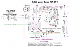
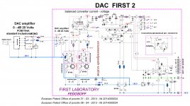
Description DAC Pre Amp FIRST - 1.. DAC chip PCM1794A switched to mono, for greater impact of current, to improve linearity and to better channel separation. With the digital zero current flowing from RSM1794A is 13 mA. Directly from the DAC chip flowing variable (sound) current (+ - 5 mA at 0 dB) is supplied to the current mirrors (on this solution has been sought in the Eurasian Patent Office.) Applied to the DAC converter circuit current - voltage on the current mirrors, provides a sound of almost any desired level without amplification stages, and it eats the main feature of DAC Pre Amp FIRST - 1. output current DAC chip manages current mirror. Precision current mirror copy control current regardless of the load resistance. Load is resistance, and resistance is the ideal inverter current DAC output voltage. Conceptually, the current mirror - it's just perfect inverting operational amplifier consisting of one transistor and which repeats the current DAC. The conclusion from the above concept is obvious that applying the required load resistance, it is possible to obtain the desired gain. Influent AC - in the current mirror transistors T1 - T8, create a variable voltage on tonkompensirovannom sound level regulator P1 and P2. The AC voltage level determined by resistors R35 and R36. The level of the AC output voltage is determined by the position of the engine control resistor level P1 and P2. In classical converters current - voltage conversion quality in the first place, the accuracy is determined by the load resistors and their value. The implementation of the inverter current - current - voltage, using a patented circuit can achieve a small load resistance, output audio of almost any desired level without amplification stages, and the use of high-precision current mirror transistors T1 - T8 allows to balance the current internal output modulators chips - PCM1794A that dramatically improves the quality of the conversion current - voltage. Current mirror transistors T1 - T8 has improved accuracy by adding the base current of the transistor T1 and T5 (equal to the base current of T2 and T6) to the output current of the transistor T4 and T8. In the emitters of transistors T3, T4 and T7, T8 are set smaller resistors. Dynamic output impedance of the receiver current emiternymi resistors considerably higher Rout = h21e x rs, current deviations are much smaller and have a value of 1/2 ^ h21e. Less critical and the scatter parameters of radioactive elements. When calculating the modes should be based on the following. RSM1794A - mono. 1 Volt AC 215 th. Mirrored current 13mA. The advantage of the scheme - a low load impedance for the modulators chips - PCM1794A, balancing internal modulators PCM1794A, tonkompensirovanny analog volume control, lack of feedback and dynamic distortion, minimal phase shift, galvanic connection.
Description DAC Pre Amp FIRST - 1.. DAC chip PCM1794A switched to mono, for greater impact of current, to improve linearity and to better channel separation. With the digital zero current flowing from RSM1794A is 13 mA. Directly from the DAC chip flowing variable (sound) current (+ - 5 mA at 0 dB) is supplied to the current mirrors (on this solution has been sought in the Eurasian Patent Office.) Applied to the DAC converter circuit current - voltage on the current mirrors, provides a sound of almost any desired level without amplification stages, and it eats the main feature of DAC Pre Amp FIRST - 1. output current DAC chip manages current mirror. Precision current mirror copy control current regardless of the load resistance. Load is resistance, and resistance is the ideal inverter current DAC output voltage. Conceptually, the current mirror - it's just perfect inverting operational amplifier consisting of one transistor and which repeats the current DAC. The conclusion from the above concept is obvious that applying the required load resistance, it is possible to obtain the desired gain. Influent AC - in the current mirror transistors T1 - T8, create a variable voltage on tonkompensirovannom sound level regulator P1 and P2. The AC voltage level determined by resistors R35 and R36. The level of the AC output voltage is determined by the position of the engine control resistor level P1 and P2. In classical converters current - voltage conversion quality in the first place, the accuracy is determined by the load resistors and their value. The implementation of the inverter current - current - voltage, using a patented circuit can achieve a small load resistance, output audio of almost any desired level without amplification stages, and the use of high-precision current mirror transistors T1 - T8 allows to balance the current internal output modulators chips - PCM1794A that dramatically improves the quality of the conversion current - voltage. Current mirror transistors T1 - T8 has improved accuracy by adding the base current of the transistor T1 and T5 (equal to the base current of T2 and T6) to the output current of the transistor T4 and T8. In the emitters of transistors T3, T4 and T7, T8 are set smaller resistors. Dynamic output impedance of the receiver current emiternymi resistors considerably higher Rout = h21e x rs, current deviations are much smaller and have a value of 1/2 ^ h21e. Less critical and the scatter parameters of radioactive elements. When calculating the modes should be based on the following. RSM1794A - mono. 1 Volt AC 215 th. Mirrored current 13mA. The advantage of the scheme - a low load impedance for the modulators chips - PCM1794A, balancing internal modulators PCM1794A, tonkompensirovanny analog volume control, lack of feedback and dynamic distortion, minimal phase shift, galvanic connection.
Hello FEDOSOFF. Thank you for the above explanation. I cannot find P2 in the schematic. Can it be actually P7 which bridges the emitters of the matched MJE340s ? The resistors R35 and R36 are at the outputs marked xxxxx for L+ and L-. What is this xxxxx output, and how do these resistors control AC voltage level? Why use a vacuum tube [operating as a buffered low pass filter] at this output instead of a bjt..? Are you seeking triode-like [instead of pentode] properties...?
Best regards.
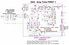
Sample application converter current - voltage.Hello FEDOSOFF. Thank you for the above explanation. I cannot find P2 in the schematic. Can it be actually P7 which bridges the emitters of the matched MJE340s ? The resistors R35 and R36 are at the outputs marked xxxxx for L+ and L-. What is this xxxxx output, and how do these resistors control AC voltage level? Why use a vacuum tube [operating as a buffered low pass filter] at this output instead of a bjt..? Are you seeking triode-like [instead of pentode] properties...?
Best regards.
Attachments
Sample application converter current - voltage.
Thanks FEDOSOFF for showing this 'simpler' schematic for further analysis, and study.
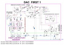
Hello FEDOSOFF. Please take a look at P14 in this simpler schematic. Should its value be 470 Ohms as shown, or 225 Ohms instead. With P14 = 470 Ohm the current mirror ratio is 1:1; meaning the collector current of either matched MJE340 is 6.5 mA. With P14 = 220 Ohms, then one gets a 1:2 mirror ratio; or 13 mA collector current for each of the matched MJE340s.Sample application converter current - voltage.
P 14 for balancing the DC voltage across R41 and R63. P8-balancing ac voltage on the R41 and R63Hello FEDOSOFF. Please take a look at P14 in this simpler schematic. Should its value be 470 Ohms as shown, or 225 Ohms instead. With P14 = 470 Ohm the current mirror ratio is 1:1; meaning the collector current of either matched MJE340 is 6.5 mA. With P14 = 220 Ohms, then one gets a 1:2 mirror ratio; or 13 mA collector current for each of the matched MJE340s.
Attachments
P 14 for balancing the DC voltage across R41 and R63. P8-balancing ac voltage on the R41 and R63
Hello, and thanks FEDOSOFF for your refined schematic. I am glad you found and corrected the typographical errors. In the interim, I had already prepared the attached schematic seeking the same clarification. I assumed that Vbe of each bjt = 0.7 Vdc, was not concerned with their base currents, and did not change the values of R39 [220 Ohm] and P14 [470 Ohm] which are connected to the emitter legs of T3 and T4.
Best regards
Attachments
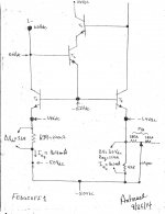
A precision current mirror. Has improved the accuracy by adding the base current of the transistor T1 (equal to the base current of T2) to the output current of the transistor VT4. 3. Èñòî÷íèê òîêà è òîêîâîå çåðêàëî №9. As the converter can be applied any other current mirror.Hello, and thanks FEDOSOFF for your refined schematic. I am glad you found and corrected the typographical errors. In the interim, I had already prepared the attached schematic seeking the same clarification. I assumed that Vbe of each bjt = 0.7 Vdc, was not concerned with their base currents, and did not change the values of R39 [220 Ohm] and P14 [470 Ohm] which are connected to the emitter legs of T3 and T4.
Best regards
A precision current mirror. Has improved the accuracy by adding the base current of the transistor T1 (equal to the base current of T2) to the output current of the transistor VT4. 3. Èñòî÷íèê òîêà è òîêîâîå çåðêàëî №9. As the converter can be applied any other current mirror.
Hello FEDOSOFF. T1 and T2 make a negative feedback circuit for T4; meaning from the collector of the matched MJE340 to its base. This feedback enhancement is absent, and/or is not known in current mirror circuits. This type of negative feedback reminds me of Schade!
Now I see your invention. T1-T4, and T5-T8 are configured as a diff OP amp. The matched T4 and T8, and their current sources [via mirroring] are new and not the classical and common ones used to date. Furthermore; the diff amp has improved performance [accuracy] by employing local negative feedback.
Question. Use T1-T4 as a current mirror load to the collectors of the input bjt diff amp circuit of uA741; which has an old style current mirror load. Will the performance of this new uA741 improve? and also use it instead as a current source to the front end diff inputs of discrete power amps. Improvement in performance?
Best regards.
: Сокровище:As the inverter circuit can be applied to the standard output.Question. Use T1-T4 as a current mirror load to the collectors of the input bjt diff amp circuit of uA741; which has an old style current mirror load. Will the performance of this new uA741 improve? and also use it instead as a current source to the front end diff inputs of discrete power amps. Improvement in performance?
Best regards.
Attachments
Is this hybrid repeater used at audio frequencies? The reason I ask is because the term "repeater" is usually reserved for RF frequencies. I've noticed that since you first posted there are only two persons communicating, Antoinel and you. Maybe it's the term "repeater" that nobody's is paying attention or commenting.
Craig
Craig
Is this hybrid repeater used at audio frequenciesIs this hybrid repeater used at audio frequencies? The reason I ask is because the term "repeater" is usually reserved for RF frequencies. I've noticed that since you first posted there are only two persons communicating, Antoinel and you. Maybe it's the term "repeater" that nobody's is paying attention or commenting.
Craig
error in the titleIt is for audio frequencies? Why is it called a repeater?
Craig
Hello Antoinel forward to your comments on the scheme in the # 30
Hello FEDOSOFF. Thank you for the schematic of post#30. It shows that the diff amp from accurate current mirrors has another; but similar applications. What are the claim [#1-7] in your patent application?. Is it a description of an accurate current mirror, or a description of a diff amp made from two matched accurate current mirrors or a description of using this novel diff amp solely for DAC applications.
One can readily use for DAC applications older style current mirrors which are not accurate, no ac feedback from T1, and T2; but will this practice infringe on your patent application?
Best regards.
Patented no specific schemes. Patented principles of the current voltage converters with non-traditional methods of conversion.Hello FEDOSOFF. Thank you for the schematic of post#30. It shows that the diff amp from accurate current mirrors has another; but similar applications. What are the claim [#1-7] in your patent application?. Is it a description of an accurate current mirror, or a description of a diff amp made from two matched accurate current mirrors or a description of using this novel diff amp solely for DAC applications.
One can readily use for DAC applications older style current mirrors which are not accurate, no ac feedback from T1, and T2; but will this practice infringe on your patent application?
Best regards.
- Status
- Not open for further replies.
- Home
- Amplifiers
- Solid State
- Hybrid Repeater in economy class A.