Hi there,
I recently built a hybrid circlotron based on a schematic by "circlotron audio". It actually works, but I'm wondering whether the MOSFET bias will be long term stable given that it is set by the constant current sources for the tubes. I'm hoping that the current feedback to the tube cathodes might stabilize the arrangement, but I'd be grateful for any feedback here as I'm sure there are some hidden gotchas.

I recently built a hybrid circlotron based on a schematic by "circlotron audio". It actually works, but I'm wondering whether the MOSFET bias will be long term stable given that it is set by the constant current sources for the tubes. I'm hoping that the current feedback to the tube cathodes might stabilize the arrangement, but I'd be grateful for any feedback here as I'm sure there are some hidden gotchas.
Nope. Tubes deteriorate over time. So direct coupling from plate to gate is a bad idea. But you can insert a cap between the plates of the triodes and the gates of the MOSFETs. But you also need to create a BIAS supply for the gates of the MOSFETs.

I was going to create a new thread but found this with lots of similarities so please don't mind me if I post my questions here:
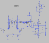
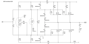
This is (part of) a commercial amp which I'm repairing, and the circuit (which I traced by myself, the maker stayed silent when I asked) shows that it is a SS Circlotron amp with tube front end.
This amp blows its power Mosfet from time to time, usually G-S shorted along with nearby parts (G, S resistors...). Replacing the damaged parts will get it running again but will fail sometime later so I wonder what causes this and what can be done to prevent this suicidal tendency.
While doing the checking around, I found that during the warmup period when the protect relay short the outputs (which takes about 30s) the bias of power Mosfets is highly unstable: Vgs of each takes turn to rise up to 15-17VDC then fall down to almost 0 then rise up again. This happen for a few cycles until both Vgs gradually settle at working level. Maybe this is the cause for mosfet blow up?
Any comment and suggestion for possible measure? I'll be gladly to answer any coming up questions.
T.I.A
Attachments
You can direct couple the stages. I don't understand why so many people on this forum get so up in arms about dc coupling. There are tons of ways to keep the circuit stable over time. DC servos, current mirrors with various feedback schemes, etc.
The problem is the overall topology is wayyyyyy past overcomplicated.
I don't know the point of Q1 or Q2. In fact it just seems like a great way to add extra noise and distortion to the output.
I see how the two mosfet pairs are acting as level shifters, but there are better ways to do that. In fact, you can incorporate a dc servo into the level shifter which would allow you to direct couple your tubes.
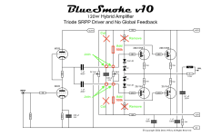
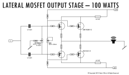
Back to basics. Use standard Circlotron MOSFET output stage for each of the MOSFETs. If memory serves: ~3.8V on the gates to get ~100mA across each of the MOSFETs. You can create a 3.8V DC supply from the DC heater supply for the 6.3V supply with a simple pot. Then have the pots viper go to each gate via say a 100K resistor. Now couple the gates to the tube section via a 1uF - 400V film cap.
Each +/- phase can be driven by a 6DJ8 in SRPP. 330 ohm resistors and a 330uF/10V decoupling cap.
So, super simple: a balanced input into two SRPPs driving 2 MOSFETs.
Should sound pretty good.
But please use delay relay to protect your speakers as tubes warm up. - a 30 sec delay should be enough.
Each +/- phase can be driven by a 6DJ8 in SRPP. 330 ohm resistors and a 330uF/10V decoupling cap.
So, super simple: a balanced input into two SRPPs driving 2 MOSFETs.
Should sound pretty good.
But please use delay relay to protect your speakers as tubes warm up. - a 30 sec delay should be enough.
The SRPP section above can certainly be applied to the + and - side of a Circlotron. Handy PCB here. One for each channel. https://www.aliexpress.us/item/3256803310088672.html
Denis
Sorry to be picky here but the way you have drawn the amplifier, I can not see the bias pot generating a dc voltage across the gates. A suggested amendment is offered. Also the 1k bias pot is too small for the chosen 100k resistors and would recommend increasing it to 10k to achieve the 3.8V bias.
Sorry to be picky here but the way you have drawn the amplifier, I can not see the bias pot generating a dc voltage across the gates. A suggested amendment is offered. Also the 1k bias pot is too small for the chosen 100k resistors and would recommend increasing it to 10k to achieve the 3.8V bias.
Attachments
Sorry to be direct: but the amplifier described as above is actually running in my listening room right now. Mind you, this is for Renesas SK1058/SJ162. Which are happy at 1.2V ~ +/- .6V.
For 3.8V and different MOSFETs, sure you have to recalculate.
The 100K resistors do not cary much current. So you are wrong there. Remember MOSFETs have a high input impedance.
But for say 8V across the two 1K trimpots, we do need to make the 15K resitors smaller. Say 3.3K each. But you better make them 5W each.
Alternatively, the two pots can be made 10X larger. As in 10K each. Then the two resistors from B+ and B- will be 33K. Keep the resistors to to the gates 100K as they form the frequency constant with the 1uF caps (sets the lower cut off frequency). Keep everything else.
Your cut and join comments makes zero sense to me. When the wire is "cut" in schematic - it just means that it crosses over. Not that it is acually cut.
So the resistors from B+ and B- (15K in my Renesas design) goes directly to each side of the pots. And the 100K "feeds" the gates from that adjustable voltage splitter. Trust me, it works. I have built more than 20 amplifiers this way. As did Moscode before me.
I realize that folks might be confused by the "break" in lines that cross - as it appears to be the case for you Ejam. So here is a slightly revised version of of the schematic. Again: this is example is for Renesas 2SK1058/2SJ162 MOSFETs.
As you can see, the pots and the 15K resistors form a symetrical voltage splitter with an adjustable null (for offset).
The 100K resistors are there to feed the BIAS onto the gates. Adjust BIAS for 200mA-300mA current draw and the offset for ~10mV on the output terminals.

As you can see, the pots and the 15K resistors form a symetrical voltage splitter with an adjustable null (for offset).
The 100K resistors are there to feed the BIAS onto the gates. Adjust BIAS for 200mA-300mA current draw and the offset for ~10mV on the output terminals.
Hi again Ejam. Thank you for the kind words on the alternative MOSFET output stage. Yes indeed there are many ways to skin the cat here. It just may be the way I drew the schematic that caused confusion.
And yes, It does indeed sound wonderful. I built the prototype in an old Hafler Pro2400 chassis that I will bring to Burning Amp this year. Hope to see you there! 🙂
And yes, It does indeed sound wonderful. I built the prototype in an old Hafler Pro2400 chassis that I will bring to Burning Amp this year. Hope to see you there! 🙂
Denis
Thanks for the replies, always appreciated and enjoyed. No confusion about the drawing. Hate to skewer you but your own diagram from BAF2019 (below) is what I put up as a suggested amendment, as you say many ways...
I see how your Blue Smoke 10 works with the gates not drawing any current, humblest apologies for not remembering this, MOSFETs being voltage controlled current sourcing devices. Given the 15k5 resistance (15kohm + 500ohm) the calculated current is 60V/15k5 = 3.9mA giving 3.9 volt drop across the 1k bias pot. By the way the 3.8V (your post 8) I assumed was referring to the gate to gate voltage, across one MOSFET the gate to source voltage would half that at 1.9V bias, which is close enough to your 1.2V +/- 0.6V. 3.8V gate to source puts it in vertical MOSFETs territory.
On a different note, last posted version of the Blue Smoke series was V5, out of curiosity what were versions 6 to 9? Also do you prefer your circlotron version BAF2023 over the Blue Smoke series?
I'd love to attend BAF and meet, unfortunately being in northern Australia and retired....but it's on my bucket list.
Peace Brother
Attachments
You are right, the BAF 2019 example of a BIAS arrangement is better. Less parts.
So here is Blue Smoke 10b with that arangement.

About sound across the series of amps in the last 15 years: each sound a bit different. Which is the fun of this hobby; we can try out diffrent combinations and listen to it. It is similar to cooking. Cook something you like. To your tastes.
The benefits of Circlotron is that it uses the same sex MOSFET for the output. The cost is 2 power supplies and the need for a balanced input.
If you do no have a balanced input, then you must add a phase inverter. Which is not a big deal - but it adds cost and complexity.
A long tail pair like the Mullard circuit here could be applied...
 So what could be done is a SRPP or single triode input with a long tail pair for phase inverter coupled to a pair of MOSFETs in Circlotron configuration. Should sound fine... 🙂
So here is Blue Smoke 10b with that arangement.
About sound across the series of amps in the last 15 years: each sound a bit different. Which is the fun of this hobby; we can try out diffrent combinations and listen to it. It is similar to cooking. Cook something you like. To your tastes.
The benefits of Circlotron is that it uses the same sex MOSFET for the output. The cost is 2 power supplies and the need for a balanced input.
If you do no have a balanced input, then you must add a phase inverter. Which is not a big deal - but it adds cost and complexity.
A long tail pair like the Mullard circuit here could be applied...
- Home
- Amplifiers
- Tubes / Valves
- Hybrid Circlotron question