Hello,
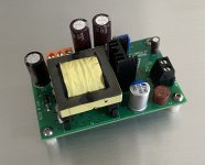
I've developed a small high-voltage DC-DC power supply working up to 500V. This board was developed to power high-power audio tubes such as the 300B, 2A3, or others power tubes.
There is a second negative output that can be used to generate the voltage required for a circuit using negative BIAS.
This can replace the traditional solution based on transformer and classic filtering.
You can check out my Github repository here: https://github.com/stefaweb/audio-psu/tree/main/HV-MODULE-UC3845-1.0
The manufacturing files are available on my Github repository in the file PCB-Board-production-1.0.zip.
For those who would like to build the board, you can find the Gerber files in the directory, as well as the BOM and position files, allowing you to manufacture the PCB assembly and SMD components directly at JLPC or another company that offers the same service.
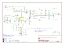
You also have the complete circuit simulation in LTSpice, which can also be downloaded from the Github repository.
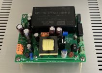
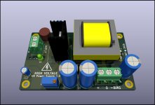
In addition to this board, I developed a second PCB that allows this power supply to be powered by a Meanwell IRM-45-24 switching power supply. This board also adds an external CRC filter for high-frequency filtering and improved ripple, a circuit to adjust the negative BIAS voltage and an external 12V power supply to connect accessories.
The files are available here: https://github.com/stefaweb/audio-psu/tree/main/TUBE-HV-PSU-45W-1.0
Enjoy!
Stef.
The characteristics are as follows:
Input: 24V
Positive Output: +180V to +500V
Negative Output: -80V to -200V (no load, only for tube BIAS)
Overcurrent protection
Overtemperature protection
Softstart (1 second by default but more by adding high value capacitor in C13')
3A fuse protection
Possibility to generate a negative voltage on the main output by modifying a few components (inverter mode).
I've developed a small high-voltage DC-DC power supply working up to 500V. This board was developed to power high-power audio tubes such as the 300B, 2A3, or others power tubes.
There is a second negative output that can be used to generate the voltage required for a circuit using negative BIAS.
This can replace the traditional solution based on transformer and classic filtering.
You can check out my Github repository here: https://github.com/stefaweb/audio-psu/tree/main/HV-MODULE-UC3845-1.0
The manufacturing files are available on my Github repository in the file PCB-Board-production-1.0.zip.
For those who would like to build the board, you can find the Gerber files in the directory, as well as the BOM and position files, allowing you to manufacture the PCB assembly and SMD components directly at JLPC or another company that offers the same service.
You also have the complete circuit simulation in LTSpice, which can also be downloaded from the Github repository.
In addition to this board, I developed a second PCB that allows this power supply to be powered by a Meanwell IRM-45-24 switching power supply. This board also adds an external CRC filter for high-frequency filtering and improved ripple, a circuit to adjust the negative BIAS voltage and an external 12V power supply to connect accessories.
The files are available here: https://github.com/stefaweb/audio-psu/tree/main/TUBE-HV-PSU-45W-1.0
Enjoy!
Stef.
The characteristics are as follows:
Input: 24V
Positive Output: +180V to +500V
Negative Output: -80V to -200V (no load, only for tube BIAS)
Overcurrent protection
Overtemperature protection
Softstart (1 second by default but more by adding high value capacitor in C13')
3A fuse protection
Possibility to generate a negative voltage on the main output by modifying a few components (inverter mode).
Attachments
Last edited:
How about you put the soft start at the 24v input with a mosfet to turn the circuit on and off. with a delay.
Or at the ic supply pin, so the mosfet won't have to run high currents.
Or at the ic supply pin, so the mosfet won't have to run high currents.
Hello,
I finally found the problem. It was really simple. I was testing the board with a load of only 1mA. The minimum for regulation to work. If I increase the load, for example, to 60mA at 350V, the softstart works.
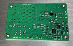
However, I'm currently adjusting the softstart to have a longer delay (between 1 second and 1 minute). To do this, I increased resistor R4 to 10MΩ and added a footprint for a capacitor on the top of the PCB. I left the 1uF SMD C13 below as base value. It will be enough to add a capacitor above the chosen value depending on the desired softstart duration.
The project is almost finished. I still have a few things to check, and then I'll publish the Gerbers on the Github repository.
Regards,
Stef.
I finally found the problem. It was really simple. I was testing the board with a load of only 1mA. The minimum for regulation to work. If I increase the load, for example, to 60mA at 350V, the softstart works.
However, I'm currently adjusting the softstart to have a longer delay (between 1 second and 1 minute). To do this, I increased resistor R4 to 10MΩ and added a footprint for a capacitor on the top of the PCB. I left the 1uF SMD C13 below as base value. It will be enough to add a capacitor above the chosen value depending on the desired softstart duration.
The project is almost finished. I still have a few things to check, and then I'll publish the Gerbers on the Github repository.
Regards,
Stef.
Attachments
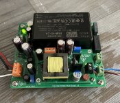
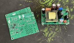
The complete power supply board.
Ripple at 350V 60mA: 45mV hot (85mV cold)
The voltage fluctuates between hot and cold by only 0.3V (thanks to the OPA810)
With the BIAS set to -60V.
Stef.
Ripple at 350V 60mA: 45mV hot (85mV cold)
The voltage fluctuates between hot and cold by only 0.3V (thanks to the OPA810)
With the BIAS set to -60V.
Stef.
Attachments
Last edited:

Hello,
I've uploaded the TUBE-HV-PSU-45W project (the large mother board) to my Github repository at the following address:
https://github.com/stefaweb/audio-psu
The Gerber files are available in the file TUBE-HV-PSU-Gerber-1.0.zip and the BOMs in the file TUBE-HV-PSU-BOM.html (to be opened with an Internet browser).
The HV module will follow in a few days. I'm waiting for new UC3845A chips from TI to verify the compatibility. The prototypes were developed with the UC3845B from ONSEMI because I had problems sourcing the original TI chips.
I've run simulations of the cost of the HV module with only the SMD components assembled by JLPCB. For 5 units, it costs €17 each (without the OPA810, which is too expensive at JLPCB). The complete module with TH components and the OPA810 costs around €45 (sourcing from Mouser or Digikey). The Wurth transformer is cheaper at Digikey, by the way.
Regards,
Stef.
Hello,
I've finished testing the UC3845A.
I didn't see any difference between the TI UC3845A and the ONSemi UC3845B. I'm going to order the boards with TI chips because the TI chips from JLCPCB are cheaper than the ONSemi ones.
I tried them with or without the OPA810, with or without the softstart circuit.
Regarding temperature, I didn't see any difference between the chips either. After 1/2 hour at 350V 61mA with a Same Sky HSE-B2111-038 heatsink (25x16x9), the mosfet temperature is 40°C.
I'm going to order the final boards, and if everything is OK, I'll post the files online.
See you in about ten days.
Stef.
Verify that the VCC voltage reaches the required startup threshold for the UC3845B. It is typically around 16V. If the VCC doesn't reach this threshold, the controller won't start, and the soft-start mechanism won't engage.
The problem was that at least 3mA of output load is required for the softstart to start the PWM. My first tests were with 1mA (the resistors included on the board by default). The threshold is 2.3V on the COMP pin.
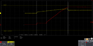
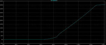
The softstart works very well now. I have a slow gradual increase in output voltage. With 1uF, we have 1.5-second delay. With 22uF, we have a 30-second delay. With 100uF, we have 2 minutes.
Stef.
The softstart works very well now. I have a slow gradual increase in output voltage. With 1uF, we have 1.5-second delay. With 22uF, we have a 30-second delay. With 100uF, we have 2 minutes.
Stef.
Hello,
I received the production version of the HV power supply as well as the PCB for the main power supply motherboard.
Everything is working as expected.
I should upload the files on my GitHub repository by tomorrow. The files include the BOM and placement files to have the PCB manufactured directly at JLCPB with the SMD components already soldered.
For those who live in the European Union, I have some spare PCBs at cost price. I do not ship outside the EU because shipping will be too expensive.
Regards,
Stef.
Attachments
Hi Jan,
This also works as a solution, at least with LTSpice. So that makes two ways to achieve a long softstart (C13 or R24). I'm keeping the C13 version, however, because it's easier to change the TH C13 capacitor on top of the PCB than to solder an SMD resistor.
I'll try it for real on the old prototype when I have some time.
Thanks.
Stef.
C13=1uF, R24=1K, R3=1M
The slope looks gentler than just with the C13 solution. Maybe a mix of 2 solutions would be even better.
Attachments
I understand perfectly, but I have other urgent matters at the moment. I'm working on a stereo solid-state driver board for power tubes like the 300B or 2A3 (to replace the input tubes).
The 1K test was just to see the effect of a "low" value.
The LTspice files are also available on the Github repository.
Stef.
The 1K test was just to see the effect of a "low" value.
The LTspice files are also available on the Github repository.
Stef.
Hello,
I just realized I haven't even posted a single picture of the power supply in operation.
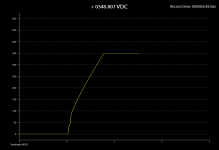
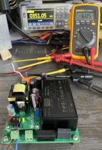
In this example, I set the HV power supply to +350V with the trimmer on the HV power supply and the negative BIAS to -60V with the trimmer on the motherboard.
Regards,
Stef.
I just realized I haven't even posted a single picture of the power supply in operation.
In this example, I set the HV power supply to +350V with the trimmer on the HV power supply and the negative BIAS to -60V with the trimmer on the motherboard.
Regards,
Stef.
Attachments
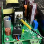
Another picture of my tests.
MOSFET temperature at 350V/60mA with a 15x10x30mm Chinese heatsink and a 1mm thick aluminum oxide plate.
Temperature after half an hour: 47°C/48°C
Room temperature: 26°C
Measured with a PT100 probe 0.3°C.
In reality it should be less because the transformer is on a support which is 10mm high and hinders the dissipation of the heatsink.
Stef.
Attachments
Last edited:
From the page on my Github repository.
Real-life testing
Output ripple at 350V 60mA: 130mV (45mV with TUBE-HV-PSU-45W power supply mother board)
24V input consumption at 350V 60mA: 1A
230V AC input consumption at 350V 60mA: 26W
Heatsink temperature: 40°C
- Home
- Amplifiers
- Power Supplies
- HV power supply using UC3845