The gyrator circuit is interesting, albeit more complex.
In particular I see that it was used with the 6SN7 (I think it should simulate a high value inductance), and distortion measurements to drive the 300b are very good.
In my case I'm dealing with the 2A3, but essentially it changes little. Maybe I'll post my finished amp in the gallery.
In particular I see that it was used with the 6SN7 (I think it should simulate a high value inductance), and distortion measurements to drive the 300b are very good.
In my case I'm dealing with the 2A3, but essentially it changes little. Maybe I'll post my finished amp in the gallery.
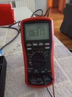
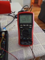
@Bela, attached gain of each channel, not too bad, 0,63mV is the SG modified for 50 ohms output impedance, 5,19mV is right channel & 5,06mV is left channel, as you can see SG set to 1kHz, it seems reach full gain x8, thanks again Bela.
Attachments

Last edited:
One NFET will form a CCS having some 1M dynamic resistance. What is the benefit of the second NFET?It all depends your lower transistor Idss.
Of course cascode.


If you are interested in more about current sources from Walt Jung articles.
The first PDF is the most interesting because it has explained cascode current sources with bias multiplier and it is also the best CCS that I have tried so far, mosfets can be; upper IXTP08N50D2, lower BSS159 or BSS139 or something completely different depending on the current and voltage drop on them.
In the picture of the Walt Jung shunt regulator, I marked CCS with Vgs* with yellow, 5V voltage drop, 130mA, BSP149 and BSS159.
Attachments
Last edited:
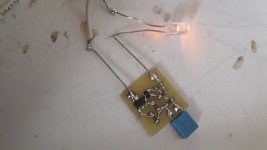
Try CCS with Vgs*, here are some from my collection. I currently have 15 different ones (from 20mA to 420mA) in my audio system(amp and DAC).
Attachments

Hello everyone,
I’m thinking to use a cascoded CCS to supply the driver directly from the first node of the B+ in a SE amp.
My target is 9 mA. I was used to see cascoded DN2540 for those currents. What are the advantages to go for other items on the bottom?
Thanks
Roberto
I’m thinking to use a cascoded CCS to supply the driver directly from the first node of the B+ in a SE amp.
My target is 9 mA. I was used to see cascoded DN2540 for those currents. What are the advantages to go for other items on the bottom?
Thanks
Roberto
By chance, they are about the same currents of mine...what kind of amplifier are you driving?
Hello everyone,
I’m thinking to use a cascoded CCS to supply the driver directly from the first node of the B+ in a SE amp.
My target is 9 mA. I was used to see cascoded DN2540 for those currents. What are the advantages to go for other items on the bottom?
Thanks
Roberto
- Home
- Amplifiers
- Tubes / Valves
- HV CCS question