"Filaments referenced to ground measures 5.8V & 7.3V both tubes."
So, you have -about-
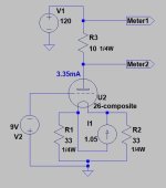
5.8V + (1.5V/2) = 6.55V bias.
The Right channel operating point is:
115V, 4.8mA
See the attached #26 curves, red and green lines intersection: it's represents about 6.75V bias. It's not too far from assumed 6.55V.

What's the problem?
The bias voltage sets the operating point.
If it's generating 115V, 4.8mA, it's working perfectly.
If you want another operating point (for example 115V, 6mA), must to set it with another bias voltage (about 6V).
Decreasing bias voltage about 0.75V: decrease 2R2 with 0.71Ohm (0.75V/1.05A)... to 1R5.
BTW did you tested the CCS with low (variable 20-50V) B+, CCS- grounded? The CCS current via R3 was stable? If not, the CCS not working perfectly.
So, you have -about-
5.8V + (1.5V/2) = 6.55V bias.
The Right channel operating point is:
115V, 4.8mA
See the attached #26 curves, red and green lines intersection: it's represents about 6.75V bias. It's not too far from assumed 6.55V.
What's the problem?
The bias voltage sets the operating point.
If it's generating 115V, 4.8mA, it's working perfectly.
If you want another operating point (for example 115V, 6mA), must to set it with another bias voltage (about 6V).
Decreasing bias voltage about 0.75V: decrease 2R2 with 0.71Ohm (0.75V/1.05A)... to 1R5.
BTW did you tested the CCS with low (variable 20-50V) B+, CCS- grounded? The CCS current via R3 was stable? If not, the CCS not working perfectly.

Yes, tested the CCS with my bench PSU lab max. 30V variable
I don't understand CCS grounded? Bench PSU connected the + probe at input CCS & - probe to output CCS....
Yes the voltage across R3 is estable, thanks.
If I understood correctly I have to change the cathode bias of each valve to match the datasheet or adjust the CCS to the minimum value of 115V to 4.8mA but if I decrease the CCS of the other valve to 4.8mA the B+ at anode will increase more....
Last edited:
Or reduce the B+ of the other valve to have 115V B+ at anode & set the same CCS of 4.8mA, that's right.
And doing the things better mod the bias of the cathode to reach the 6mA with 115V B+ at anode for both tubes and surely reducing the B+ of the other valve before the CCS to have the same 115V B+ at anode
And doing the things better mod the bias of the cathode to reach the 6mA with 115V B+ at anode for both tubes and surely reducing the B+ of the other valve before the CCS to have the same 115V B+ at anode
Last edited:
Silly me! I always guessed the CCS set the operation point of tubes no taking into account the grid/cathode bias and also it's necessari to fix the ànode B+, I was really really lost😱
Yes, tested the CCS with my bench PSU lab max. 30V variable
I don't understand CCS grounded? Bench PSU connected the + probe at input CCS & - probe to output CCS....
Bench PSU connected the + probe at input CCS & - probe to output CCS to PSU negative.
Set PSU to 30V, then 25V, after it 20V.
If the voltage on 10R is stable, the CCS working well.
Bela to reduce the different voltage between tubes I guess it's a good idea to use a RC at the input of the tube with more voltage to reduce the volts at the anode after the CCS.
Difference to reduce the voltage is 7V/0.012 = 1167 ohms
Are OK my maths?
Difference to reduce the voltage is 7V/0.012 = 1167 ohms
Are OK my maths?
Why does bother you few Volt difference?
Tube condition differs, so Ua with constant current also differs, but these tubes working in individual channels.
The tight tracking (between tubes) only important in case of paralleling.
Tube condition differs, so Ua with constant current also differs, but these tubes working in individual channels.
The tight tracking (between tubes) only important in case of paralleling.
Correction 7V/0.006A = 1.167 ohmsBela to reduce the different voltage between tubes I guess it's a good idea to use a RC at the input of the tube with more voltage to reduce the volts at the anode after the CCS.
Difference to reduce the voltage is 7V/0.012 = 1167 ohms
Are OK my maths?
The tubes are differs.
If you swap tubes, the Ua swapping too, and the Ua difference also swapping.
Not sure that same amount, because bias may also differs (diode saturating voltage, small resistor value).
Try it.
Measure the R.C. regulator (for example at 1A) feeds only filament bias elements (R-D-D) -without tube-, and measure voltage on its.
Be sure, that tube's filament parameters are -close- equals.... as much as possible (selecting tubes from large batch).
These old tubes filaments can be very different, the heating wire may thins out, the hot resistance may growing.
If you use different tubes, the same filament current generates different filament voltages, so in case of DH tubes the -assumed- "half of filament voltage" also differs.
All of parameters impact filament biased tube behaviour.
If you want to measure filament biased tube concrete operating point (assumed Ua, Ia, Ug, in accordance with datasheet) use these:
- use direct filament heating (DC, R.C. regulator);
- use equal small resistors (few-few ten Ohm) from filament end to bench PSU (capable few hundred Volts) negative;
- set it filament voltage;
- use specified negative voltage on grid;
- connect bench PSU positive to anode (with current sensing 10R resistor, or without it, if PSU can measure current);
- set bench PSU voltage to assumed Ua;
- measure the real Ia.
Last edited:
TL431 is good to use to in tandem with an enhancement Mosfet like the irfbc20....2.5/20ma =125 ohms, source sensing..
https://www.ti.com/lit/an/slva987a/...94822&ref_url=https%3A%2F%2Fduckduckgo.com%2F
https://www.ti.com/lit/an/slva987a/...94822&ref_url=https%3A%2F%2Fduckduckgo.com%2F
"why the 6V of difference between valves matched with a difference of 0.02mA!!!!"
It's only static parameter, but correlating with tube condition.
With same bias, same current the anode voltages differs: one tube weaker, than another, emits lesser electrons.
If you measure gm, the tube where Ua is lower (it's stronger) shows higher gm.
For example I measured several 801/801a tubes: fixed Ug (-9V), fixed Ia (400V B+, 18mA CCS).
The minimum and maximum Ua was 158V and 232V.
These tubes gm was 1810 and 1639.
If it (different Ua) bother you, try to change 2R2 (for example paralleling with 10R...4R7), to changing bias.
The anode voltage will changing, but tube's gm practically remains as above (mutual conductance would changing about 5% -see datasheet-) , so one tube will produce a little lower output than another.
Now I understood what you want I do: only to change the right channel to get 6mA & don't do nothing to the left channel because still having different anode B+ voltage have the 6mA, right?
1st I will try changing the 2R2 to 1R5 at filament bias
1st I will try changing the 2R2 to 1R5 at filament bias
No.
Use same anode current (CCS), and slightly change in one channel the filament bias (decreasing 2R2, increasing Ua).
It deals less damage than using its with different current.
1.) But before do anything: are you measured both channels with the same (for example 1V) input? Is noticeable (few dB) difference between output voltages?
2.) Are you tested both tubes in the same channel (measured static voltage, anode current, and mostly output volume)?
Last edited:
- Home
- Amplifiers
- Tubes / Valves
- HV CCS question