I have a Knight Kit KG-664 which is a close relative that uses 4 X 6L6GC tubes and a bigger transformer to deliver a rated 200 mA. The panel meter has a red zone extending to 300 mA, and operation in this area for short periods of time does not cause problems. The supply will hold 400 volts at 300 mA. There is a pot inside that you can turn up to get a bit more voltage, but this will cause the supply to drop out of regulation above 250 mA and 400 volts. Perhaps some better output tubes (TV sweep tubes) would allow more output since they have more Gm and a lower saturation voltage. It works and fills my needs, so other than a recap and some fresh tubes a few years ago, I haven't messed with it.
I also have a Fluke 407D which goes to 555 volts at 300 mA. It is completely original except for the meter switch which I repaired with JB weld. It will do 550 volts at well over 400 mA before it goes into convulsions (low frequency instability) A big fat cap across the output can extend this a bit, but then you get into the area where something inside starts smelling funny. I have not found a schematic for the 407D yet, but the older 407 schematic is on the web. The obvious difference is the number of pass tubes. The 407 has 3 X 807's, and mine has 5 or 6, I don't remember exactly haven't had it open in at least 10 years. The 407 schematic does show a more complex error amp than the old Eico, with a 12AX7 diff pair driving a 6AU8. It also uses a tapped power transformer to reduce pass tube dissipation at low output voltages.
Pete Millett took the Eico design one step further in his vacuum tube power supply design. Still shoots for 400 volts max output though.
High-voltage bench supply
Attachments
It's pretty stable. I need to do one more round of testing with the final six mosfet configuration, but so far things look good with a 3.3nF cap in place of C7. I can't get it to oscillate into capacitive loads. Once I finish the thermal part I will be able to do some proper abuse testing to see just where it has issues, though from the testing I have done I feel pretty good about the stability.
Good point on the opamp protection, maybe a 10v zener in parallel with R13?
Good point on the opamp protection, maybe a 10v zener in parallel with R13?
I posted this EDN article link -- I did build a prototype which worked --
http://www.edn.com/design/power-man...-500V--10-mA-power-supply-in-a-different-way-
It certainly can be extended for much higher currents. If anyone cares I have a dozens of BU208a's.
http://www.edn.com/design/power-man...-500V--10-mA-power-supply-in-a-different-way-
It certainly can be extended for much higher currents. If anyone cares I have a dozens of BU208a's.
That's a nice design Jack! I have been playing with something similar with the HCNR200 (~IL300) but the available current from the photovoltaic diodes was not large enough to drive a big MOSFET with its large capacitance. This discrete optocoupler seems a nice solution. But I wonder about the hf performance, it may have a large inductive Zout.
In the end I solved the dilemma by floating the whole control section on the high voltage output voltage. Works fine too 😎
I'll publish it in due time.
Jan
In the end I solved the dilemma by floating the whole control section on the high voltage output voltage. Works fine too 😎
I'll publish it in due time.
Jan
That's a nice design Jack! I have been playing with something similar with the HCNR200 (~IL300) but the available current from the photovoltaic diodes was not large enough to drive a big MOSFET with its large capacitance. This discrete optocoupler seems a nice solution. But I wonder about the hf performance, it may have a large inductive Zout.
In the end I solved the dilemma by floating the whole control section on the high voltage output voltage. Works fine too 😎
I'll publish it in due time.
Jan
I have tube of IL300 left over from a project -- nice but slow. I think that the application notes for the HCNR200's are from the era in which the company was still Hewlett Packard!
In this case you can use a higher voltage gate driver, and if you're testing stuff, not building an amplifier, they are sufficient to operate the MOSFET.
I think the best solution is SMPS with a slew adjustable driver chip like the LT1683.
If I needed more than about 400mA for sustained periods I would do what some of the power supplies at work do where they use a PWM circuit and some SCRs to do the switching, then an LC circuit to smooth it. A linear regulator drops the last 20v volts to get an accurate and quiet output.
In my case, I wanted another HV bench supply and I wanted to see if I could make a fully linear design like this work.
In my case, I wanted another HV bench supply and I wanted to see if I could make a fully linear design like this work.
To reawaken this thread I will mention that I have been working with a DIY vacuum tube curve tracer / test system to replace or supplement the Vacutrace that I have been using. The Vacutrace has several shortcomings that I discussed in the Curve tracer thread, so I started kluging together something to address those issues.
How-to article presenting a practical tube analyzer
This started out as a breadboard filled with opamps, mosfets, and several off the shelf Chinese power supplies from Ebay and Amazon all connected to the Vacutrace. Some of the little power supplies, especially those 0-380 volt boost converters have failed in spectacular manner, so I dragged out the old breadboard I talked about in post #12.
It didn't take me long to stumble across the SOA limitations discussed here, and I have blown up several of the big Fuji fets, and a few other TO247's that I happened to have handy. The power supply would indeed survive a momentary short across the output, but blow rather quickly when asked to provide a 200 mA constant current at relatively low voltage.
As H713 stated here, and in the EEV blog posts, the SOA ratings published by the semi vendors are not to be trusted. This is especially true with anything from ON / Fairchild, since their published curves exactly match the full device dissipation rating for all voltages. Some of the parts from ST micro have believable SOA charts.....that reveal horrible performance.
So after several hours of looking at data sheets, I found these $6 IXYS 300 watt parts. No idea if they will actually perform at this lever, but the data sheet specifically states a "Safe-Operating-Area Specification" on page two of the data sheet, that says Vds = 800V, Id = 225 mA, Tc = 75C, Tp = 5S with a minimum spec of 180 watts. This agrees with the curves in the sheet which seem to indicate about 275 mA at 650 volts. These are Depletion Mode mosfets which will require a little circuit modification. I will order a couple to see how they really work.
The backup plan seems to be several fets in series so I'm looking for some fets that will eat say 75 to 100 volts each at over 1 amp.
To reawaken this thread I will mention that I have been working with a DIY vacuum tube curve tracer / test system to replace or supplement the Vacutrace that I have been using. The Vacutrace has several shortcomings that I discussed in the Curve tracer thread, so I started kluging together something to address those issues.
How-to article presenting a practical tube analyzer
This started out as a breadboard filled with opamps, mosfets, and several off the shelf Chinese power supplies from Ebay and Amazon all connected to the Vacutrace. Some of the little power supplies, especially those 0-380 volt boost converters have failed in spectacular manner, so I dragged out the old breadboard I talked about in post #12.
It didn't take me long to stumble across the SOA limitations discussed here, and I have blown up several of the big Fuji fets, and a few other TO247's that I happened to have handy. The power supply would indeed survive a momentary short across the output, but blow rather quickly when asked to provide a 200 mA constant current at relatively low voltage.
As H713 stated here, and in the EEV blog posts, the SOA ratings published by the semi vendors are not to be trusted. This is especially true with anything from ON / Fairchild, since their published curves exactly match the full device dissipation rating for all voltages. Some of the parts from ST micro have believable SOA charts.....that reveal horrible performance.
So after several hours of looking at data sheets, I found these $6 IXYS 300 watt parts. No idea if they will actually perform at this lever, but the data sheet specifically states a "Safe-Operating-Area Specification" on page two of the data sheet, that says Vds = 800V, Id = 225 mA, Tc = 75C, Tp = 5S with a minimum spec of 180 watts. This agrees with the curves in the sheet which seem to indicate about 275 mA at 650 volts. These are Depletion Mode mosfets which will require a little circuit modification. I will order a couple to see how they really work.
The backup plan seems to be several fets in series so I'm looking for some fets that will eat say 75 to 100 volts each at over 1 amp.
I fought with this for the better part of a month (of weekends).
The conclusion I came to is that lower voltage FETs handle linear operation better than the HV FETs I tested. I tried several different 900V and a few 1200V FETs that looked promising but turned out to handle at most 150mA with 400V across them.
IRFP460s proved to probably be the most useful part. Running six of them in series, it was able to take over an amp without failure. Since this is current limited and fused at 500mA, that's fairly safe. At 1 Amp the DC bus sags down to something like 450V or less.
The other problem I ran into with parallel FETs is that they do not current share very well- one or two would always hog the current and blow up.
I believe those IXYS parts are what we used at the lab for the dump modules in our programmable power supply project. Four of them in parallel were used (switching, of course) to dump one bank (about 250 millifarads @450V) into a big 25 ohm resistor. As far as I know they didn't have any issues with these particular FETs blowing in that application. I expect they will be pretty tough.
Ultimately I chose to use the series FET solution because I felt that it put the least stress on the MOSFETs. So far that PSU hasn't failed, even when it got used for testing some tubes that turned out to be extremely gassy (Turns out an 829B can become a thyratron😱).That said, I took a lot of care in the thermal interface so those FETs run pretty cool.
The other problem I ran into with parallel FETs is that they do not current share very well- one or two would always hog the current and blow up.
Even with fairly large source resistors one gets greedy and dies, then bad stuff happens since silicon almost always fails to a short.
For years it was believed that mosfets did not suffer from secondary breakdown. ON / Fairchild must still believe this since their SOA curves seem to based solely on dissipation.
In the last 12 years of mu engineering career at Motorola I was a transmitter designer in an advanced research group. For the last three years myself and another engineer had designed a transmitter for a hand held walkie talkie that covered 136 to 941 MHz and produced about 8 watts of RF power. We used a GaN fet that was rated for 50 watts of RF output in "long pulse radar." The vendor assured us that there would be no problems.
Unfortunately a transmitter could undergo all sorts of extreme torture testing, with no failures, and then just blow under the most mundane conditions. Flir microscope video of the parts running looked normal sometimes for weeks of constant operation.....then a localized hot spot would develop and poof, the part was dead, all in under a minute. We worked with the vendor on this for nearly two years, then I got the 'offer you can't refuse" and left the company. Now after a few more years the product is shipping, and it uses a new version of the same part.
I looked at a lot of mosfet data sheets today, and ordered a few IXYS parts, both the depeletion fets, and the smallest of the linear rated fets. I will be testing some once they arrive.
Turns out an 829B can become a thyratron
So can a TV sweep tube, a really big one. It was responsible for the death of three of the big Fuji fets….yes, I was dumm enough to try it three times.
I plan to build a series wired pass circuit with the $2.49 IXYS linear mosfets first, because I will blow some up. THEN I'll upgrade to whatever the circuit needs. It seems that the real SOA of most of those linear rated IXYS fets, and some of their depletion mode fets is about half of the specified dissipation in the middle of the linear region. For $24 each they offer a BIG fet rated at 960 Watts of dissipation, but it's good for 2.3 amps at 250 volts, and 5.7 amps at 100 volts.
I'm still planning to start with the same design I posted earlier, since it works, and is easy to control with an Arduino compatible board. The end application is a curve tracer that can push the non-thyratron versions of these big tubes well beyond 100 watts of dissipation.
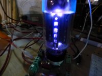
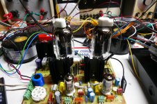
Here's a picture of a little test Single Ended test amp squeezing over 40 watts of audio through each channel with 36LW6's. They are running a bit over spec (more than 100 watts) but they ran that way all day long. The real amp will use two tubes per channel.
Attachments


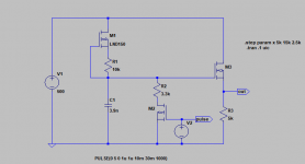
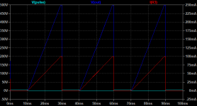
So, if we are curve tracing, here's an idea incorporating an application note on the LND150 DMOS with VN055 low power NMOS for a high voltage ramp -- to drive the gate of a high voltage, higher power MOSFET. You can adjust the pulse on-time to keep within the confines of the safe operating area.
Attachments
- Home
- Amplifiers
- Power Supplies
- HV bench power supply design