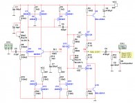
Take a look at the Simplified schematic.
There is nothing strange, but the difference is the CFP output.
The distortion is low when we finetune the quiescent current.
THD 0.000058% at 1 Watt in 8 Ohm.
The circuit uses only transistors that are possible to buy.
Power Supply should be a transformer 2x22VAC.
Each winding rectified for each channel.
Attachments

https://www.diyaudio.com/community/threads/is-cfp-better-than-ef.270062/ has some discussion on "CFP"...
Simple fun amplifier.
For simplified model should work fine.
In real life, likely needs emitter resistors for current mirror.
Value depends on overall current.
Should have about 50 mv drop over resistor.
C4 seems excessively high.
Adding degen resistors for U8/U9
could improve high frequency stability issue.
overall very interesting.
because was just modeling something very similar.
for some strange reason was also interested in
making simple single supply amplifier.