Hello Everyone,
I am having some difficulty with hum in a push pull amplifier I am working on. The amp powers up correctly, the B+ voltage reads about 10 volts above what I modeled during my design calculations, and everything seems OK with respect to component temperatures, capacitor polarities, etc. -- i.e. I didn't get electrocuted and the amp didn't catch fire.
But, there is a nasty hum present once I went to attach speakers (although I can hear a signal alongside the hum if I apply one).
If I ground the input grid to the first voltage amplifier stage (plate resistor loaded 12AX7) by turning the input volume potentiometer all the way to zero, there is no hum. The signal lead is taken off of the wiper, so turning up the pot increases the resistance between grid input and ground. As anticipated, the hum volume audibly increases as I turn up the volume pot. Can I interpret this as meaning that the hum is originating by some unwanted noise being imposed on the input stage's grids? Both channels exhibit similar hum.
I'm trying to rule out heater current inducing hum insubsequent stage's grid connections, tube imbalance, transformer shielding, etc., by virtue of the fact that grounding the first input stage's grid eliminates the hum.
Before I tear everything apart, some details about the circuit from input to 12AX7 grid:
-1k grid stopper
-100k volume pot, signal taken from the wiper
-0.2 uF film capacitors to attenuate DC
-26 AWG shielded cable from RCA jacks to input selector. Shields are connected at one end to the aluminum chassis. Cutting the shield connection didn't help anything.
-Both input selector and volume pot bodies are earthed by virtue of their contact to the aluminum chassis. Ditto the RCA jack's body. Initial signal inputs were with an iphone not connected to its charger. The hum is present without any input device connected to the RCA jacks.
-All signal grounds join at a single bus, which is then connected to a grounded bus in the power supply turret board. This is connected to IEC neutral. I am using an IEC plug with the earth connected to the chassis and no connection between chassis and neutral.
Any suggestions?
Signal ground (indeed, any ground) shouldn't be connected to mains neutral. Remove that.
If the RCA body is grounded, use that as your only signal ground connection to the chassis. Or use an isolated RCA and ground at some other point.
If the RCA body is grounded, use that as your only signal ground connection to the chassis. Or use an isolated RCA and ground at some other point.
In addition, it seems like your selected input in not shorted to ground at its RCA socket, so you be amplifying pot/etc noise when input vol wiper is increased, so you will hear noise/hum of some level until you connect an input signal source of low impedance.
If your input jacks are grounded at the chassis and at the power supply bus, you have a ground loop. I would ground to chassis at the power supply bus only. IEC neutral should never be connected to chassis. Use IEC safety ground (green) to chassis only at closest point of entry. And don't connect power supply ground and IEC safety ground at the same point on the chassis.
Is there a schematic of your amplifier?
A picture is worth 1000 words.
Sounds like a ground loop to me.
Some ground loops are combinational, like a B+ ground loop interacting with an input circuit ground loop.
I design and build single ended and push pull vacuum tube amplifiers that have 100uV or less hum at the 8 Ohm tap.
A few have been more stubborn, and had as much as 500uV (0.5mV).
Every detail has to be accounted for to get the hum down to 100uV.
How much hum are you getting?
Oh, and you said when you connected the speakers you heard the hum.
Always have a proper resistor load or a loudspeaker connected to the output.
Last edited:
Ok so the first reply seems to have nailed most of the problem here. The connection between neutral and signal ground at the power supply ground was all it took to fix it. That said I did rewire shielded cable, grounded at the RCA jack, to the input selector switch. The RCA jacks are grounded by contacting the Al chassis.
Hum, before these adjustments, measured about 160 mV PtP, at almost exactly 120 hz.
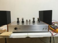
I haven't done much more quantitative testing. As soon as I heard the hum was reduced I immediately started listening to music through the amp. Maybe I'll take some more measurements later in the week. First I want my ears to decide if they like my design. Picture attached with the bottom cover removed so I could attach leads to B+.
Also @6A3Summer, I did ensure a load was connected at all times, there was a shut the amp off, let everything cool, attach load step I didn't mention. Thanks for the warning though.
Thanks guys
Hum, before these adjustments, measured about 160 mV PtP, at almost exactly 120 hz.
I haven't done much more quantitative testing. As soon as I heard the hum was reduced I immediately started listening to music through the amp. Maybe I'll take some more measurements later in the week. First I want my ears to decide if they like my design. Picture attached with the bottom cover removed so I could attach leads to B+.
Also @6A3Summer, I did ensure a load was connected at all times, there was a shut the amp off, let everything cool, attach load step I didn't mention. Thanks for the warning though.
Thanks guys
Attachments
Cool!
In case you didn't realise, mains neutral is tied to mains ground (only!) at your house main circuit board. So, you had created a loop by tying that back to the chassis via the signal ground. It's also unsafe (any number of wiring faults could put the user at risk of electrocution)
Although mains neutral is technically grounded, the potential can be quite different from the safety ground at the wall socket, as the neutral carries current and safety ground does not (only a small amount of leakage etc) except under a fault condition.
- Home
- Amplifiers
- Tubes / Valves
- Hum Troubleshooting Path