It will be sufficient to only change the connections on your current board for the test. If it works out, you can still make a different PCB later.kin said:I have to do a completely different pcb because I have 4 discrete ultra-fast bridges + soft-start and stand-by circuitry on the same board. But i'll certainly try it if I don't find any other solution.
But it may still be necessary, when the rectifier rewiring turns out to reduce your problem significantly without curing it entirely.kin said:I must admit that I also was crazed with separation of dirty ground from signal gnd with 10 ohm rez, but that didn't work.
Hello again!
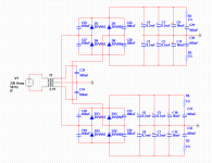
I have stared a new PS layout, and this time i'm using only 2 discrete bridges and for the soft-start and other auxiliary circuitry i'll be using another board. Before building it, i thought to ask around here for opinions on my layout so i'll be posting the schematics and the layout. A few words about it, on the top layer i have routed the AC signal and on the bottom the DC and GND. The file with the bottom layout contains also the silkscreen and info. What suggestions do you have?
I have stared a new PS layout, and this time i'm using only 2 discrete bridges and for the soft-start and other auxiliary circuitry i'll be using another board. Before building it, i thought to ask around here for opinions on my layout so i'll be posting the schematics and the layout. A few words about it, on the top layer i have routed the AC signal and on the bottom the DC and GND. The file with the bottom layout contains also the silkscreen and info. What suggestions do you have?
Attachments
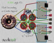
Why not? I use the bridges between the two ends of the winding and the center-tap is grounded. Well, my trafo is not center-taped, it has two distinct windings but i will wire it that way. Basically I use this scheme:
http://sound.westhost.com/project04.htm
http://sound.westhost.com/project04.htm
pacificblue said:You cannot use two bridges with a center-tapped transformer.
Why?
Adcom's GFA555 used this arrangement. Although it looked like separate windings for the two bridges when one dug into the transformer it was two sets of wires coming from a single center-tapped secondary. This amp produced 200 watts per channel into 8 ohms and not an insignificant number of them were sold this way.
Yes you can, and it is infact a very good solution for power amps 😉You cannot use two bridges with a center-tapped transformer.
There are center-tapped transformers and dual secondary transformers. You can use both types of transformers with a single Graetz bridge to create a split power supply or you can use a dual secondary transformer with two Graetz bridges to create a split supply. If you try to create a split supply with a center-tapped transformer and two Graetz bridges, you will unavoidably get shorts across both halves of the secondary through one diode on each bridge.Jan Dupont said:
Yes you can, and it is infact a very good solution for power amps 😉
I have to admit that I didn't read the schematic from post #22 right before posting. It repeats the same mistake from the beginning. If you want it hum-free, you need to create one split supply and connect the amplifiers in parallel to that. If you want two split supplies, you need two transformers.
pacificblue said:.... It repeats the same mistake from the beginning. If you want it hum-free, you need to create one split supply and connect the amplifiers in parallel to that. If you want two split supplies, you need two transformers.
What would be the reason for that? Last time there were 4 bridges connected two in parallel for each winding and the gnds separated. Now I have a single gnd and two bridges in parallel between + and -, and any current that should flow through gnd would be generated by the imbalance in transformer(witch it is pretty small, i use a Talema trafo and i have measured it). However I wish to contain this current not to flow where signal return currents flow. That's why I posted the layout, do you think it is ok?
In your first schematic you used a dual secondary transformer with four bridges. Now you use a center-tapped transformer with two bridges. So you changed two parameters at the same time, when you should only change one at a time.
Your actual schematic will probably produce less hum than the first, but it cannot be guaranteed to be hum-free. The imbalance in the transformer is not the only source of currents to ground. The ground potentials between the capacitors will be determined by the voltage drop in the diodes and the capacitor impedances. It is very unlikely that they are exactly the same for the upper half and the lower half of your power supply. So you will get three different ground potentials that will try to level out. If you use a common star-ground for both channels you could get away with it, although the ground will always be 'wandering', because different load situations will lead to different potentials at the three points. The better solution is to use one split supply, preferably from a dual secondary transformer with two rectifier bridges. But even with a center-tapped transformer and a single rectifier bridge you should get better results, because there are only two potentials to level out, the center-tap imbalance and the ground potential of one set of rectifiers and capacitors.
If you use the first schematic, skip two bridges. If you use the latest schematic, skip one bridge. In both cases connect the capacitor banks together. Use one star-ground for both amplifier channels. You can separate the capacitors later and add the other bridges, when you add another transformer or replace the one you have with one that has double the amount of secondaries.
that diagram of a Nap must be wrong.
It surely cannot have the main Audio Ground on the smoothing cap Zero Volts point.
The Star Ground including the Speaker Return should be separate from the PSU Zero Volts point. Even a 1mm separation (the thickness of a PCB) makes a difference.
It surely cannot have the main Audio Ground on the smoothing cap Zero Volts point.
The Star Ground including the Speaker Return should be separate from the PSU Zero Volts point. Even a 1mm separation (the thickness of a PCB) makes a difference.
The second version is somewhat like the first, the pcb signal gnd is not connected in the same point as the center tap, but, i fear that the pcb strip connecting the capacitor gnds that carries heavy pulsed currents will affect the pcb gnd. What is your advice on this?
Attachments
kin said:I fear that the pcb strip connecting the capacitor gnds that carries heavy pulsed currents will affect the pcb gnd. What is your advice on this?
In both layouts the charging currents as well as the speaker return currents will influence the signal grounds.
Yes, I think you are right. If I route those singal Gnds on the top layer directly to the star with their separate tracks will it be ok then?
Hi
Information on following URL is offered as a reference information.
Consideration of hum noise decrease in twin monaural construction
The summary is a technology of severing the loop by the voltage gap of the diode.
There was a technology that looked like the amplifier of ONKYO before.
http://www.ne.jp/asahi/evo/amp/J200K1529mono/rep.htm
Regards!
- Status
- Not open for further replies.
- Home
- Amplifiers
- Solid State
- Hum problem with pseude dual mono amp