I recently built a PAS variation. A Tubes4Hifi Aikido tube preamp made for a PAS enclosure. I am have a hum issue. I used their power supply update as well. The hum varies in how loud it is depending on where the volume is set. However every once and a while it increases in how loud it is. It stays louder for a couple minutes then dies down again to the level it was at before. I have replaced all the new 12au7's with another new set but that has no affect on the situation. I have put a cheater plug on it, reversed the way it was plugged in with no affect. All my equipment is plugged into the same power conditioner. I do not believe it is a ground loop hum. Any one out there that might be able to help me figure out where this is coming from?
Thanks,
Mark
Thanks,
Mark
Hum is 60 hz, yes I have a scope. But I have only used it a few times. May I ask what does the 60 hz vs 120 hz mean?
Thanks,
Mark
Thanks,
Mark
Last edited:
120Hz and 60Hz hum will have different origins, so it's useful as a first step to determine which it is. 120Hz usually comes from power supply wiring and layout, especially if signal circuit grounding isn't optimal- it's the major ripple component from rectifying 60Hz. 60Hz usually comes from a ground loop or pick up of radiated hum.
What part of WI are you in?
What part of WI are you in?
Nice town, home of Harry Houdini.
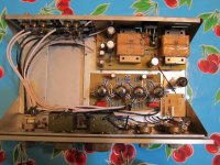
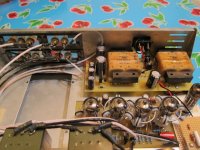
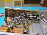
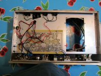
We're up there every couple of weeks (just there yesterday), if we can't get it sorted out via the forum, I can walk you through it if you like. Photos of your layout and wiring would help, as would a screen shot of what the hum on the output of the preamp looks like on your scope.
We're up there every couple of weeks (just there yesterday), if we can't get it sorted out via the forum, I can walk you through it if you like. Photos of your layout and wiring would help, as would a screen shot of what the hum on the output of the preamp looks like on your scope.
Sy, that would be great if you are in this neck of the woods for you to stop by. Any time even if I don't have the issue any more.
Unfortunately one of my amps went down the other day, so it may be a while before I get it back.
Been a while since I loaded an image any tips?
Unfortunately one of my amps went down the other day, so it may be a while before I get it back.
Been a while since I loaded an image any tips?
Yeah, it's pretty easy. Scroll down in the Reply screen to the "manage attachments" button. It's pretty intuitive from there. Keep the image size under 200k or so.
I see you're in the coffee biz. Excellent, I'm a bit of an enthusiast...
I see you're in the coffee biz. Excellent, I'm a bit of an enthusiast...
For some reason, I could open the image from the notification mail I got 🙂. The wiring is up for some improvement. The twists on what as far as i can determine is the heater cabeling need to be WAY tighter for any EMI cancelation. The heater supply needs to be balanced as well by an (artificial) center tap. The lenghts of almost every cable could be shorter as well. I suspect this is how the 60Hz interference is getting into your signalpath.
Sy, yes I like coffee quite a bit. I just got some wonderful Yirgacheffe in. Not sure how you feel about lighter roasts, but this has a nice raspberry tart finish that really lingers. I and my wife really like it. We will see what the public thinks of it in another 8 days.
My coffee tastes are quite catholic- the Yirgacheffe sounds intriguing! I need to get up there...
OK, a few questions:
1. Where is the safety ground (i.e., the chassis bond from the power connector ground)?
2, Are the input and output connectors isolated from the chassis? Where are their grounds returned to?
3. Where does the signal ground meet the chassis?
4. Where does the power supply ground meet the signal ground?
1. Safety ground is currently connected to chassis where the IEC mounts.
2. Yes inputs and outputs are isolated. Their grounds are returned to the PCB.
3. Signal ground meets the chassis at the PCB, the PCB ground contacts the chassis.
4. I am not certain on this answer, but I think it is at the 12x4 tube socket.
2. Yes inputs and outputs are isolated. Their grounds are returned to the PCB.
3. Signal ground meets the chassis at the PCB, the PCB ground contacts the chassis.
4. I am not certain on this answer, but I think it is at the 12x4 tube socket.
Can anyone give me an idea what would cause the intermittent increase in hum. I don't understand how that can happen, unless it is a tube or capacitor.
I would look at the input circuit. too low of a grid to ground or even grid input resistor will give you this effect as the impedance mismatch destabilize bias until the input coupling capacitor charges. too low of an input grid to ground and in series with the grid can cause this sensitivity issue when using Ac powered heaters. hum balancing and B+ referencing is important as well.
A little note about this amp design. It was prototyped on powering the heaters with a lead acid battery as the heater supply.
A little note about this amp design. It was prototyped on powering the heaters with a lead acid battery as the heater supply.
Carefully check (maybe even redo) your solder connections as well. Also: the power supply feed to circuit board ground should come directly from the minus terminal of the supply output capacitor- that's a common route for inadvertent ripple injection.
Someone has suggested that I short the inputs to verify the hum is being caused by the preamp. Upon doing that all hum stopped, totally quiet.
- Status
- Not open for further replies.
- Home
- Amplifiers
- Tubes / Valves
- Hum issue in PAS Aikido