input circuit could be improved. values they used are arbitrary
try:
r10 and r11: 1K and r6&r7 470k
try:
r10 and r11: 1K and r6&r7 470k
Those values are unlikely to make any difference. Values of grid leaks and grid stoppers can be varied quite a lot without affecting anything.
Sam, this is actually a great idea to check the buzz/hum with input twisted pair discinnected. I just tried it and both channels are perfectly silent.
I have input impedance 27k but I believe it will not be much worse with original 1 M.
So I think it is clear that the issue is input wiring from back pannel to input terminal on the PCB.
I will try to elaborate with capacitors as you recommended now.
I have input impedance 27k but I believe it will not be much worse with original 1 M.
So I think it is clear that the issue is input wiring from back pannel to input terminal on the PCB.
I will try to elaborate with capacitors as you recommended now.
Hi!
Great that you are making progress with the combined help of the forum. Excellent advice given by Sam on the remaining issues.
Best regards
Thomas
Great that you are making progress with the combined help of the forum. Excellent advice given by Sam on the remaining issues.
Best regards
Thomas
Vcelkamaja, I was doing some late night reading and stumbled across something that might interest you. I have a hard-copy of the Radiotron Designers Handbook, 3rd Edition (sadly, not the legendary 4th edition...), and on page 11 the author mentions a hum problem very similar to the one you experienced.

The circuit is a simple phase splitter. Since R1 and R2 are approximately the same value the triode V2 cathode is at a relatively high voltage with respect to ground. The high cathode voltage is exactly the condition that the upper triode in your amplifier SRPP stack has - which is why I found this to be applicable to your situation.
The author states that "... hum may be troublesome. Part of the hum is due to the considerable difference of potential (voltage) between the heater and cathode V2. This (the hum) may be reduced by operating the heater of V2 ... connected to a suitable point in the circuit which is at an average potential (voltage) approximating to that of the cathode. "
In plain (i.e. - American 🙂) English, the author is suggesting to bias the heater up closer to the cathode to reduce hum. By putting in your bias network to raise the heater voltage closer to the cathode potential, you have implemented exactly this correction!
This is one of those rather "not-obvious" conditions that can cause trouble in these tube circuits. I am particularly surprised that the kit-design did not take this into consideration - the design itself should have relieved you of the trouble of this type of troubleshooting. This is more a case of what you might encounter when designing your own amplifier - unintended consequences and all that.
Well, at least it has been a very good learning experience! I have certainly learned a lot, watching over your shoulder! And I'm certain others who read in here might pick up something new, too - it's just too bad the original design didn't allow you to build your amp and start enjoying it right away!
But I believe that once you have solved the remaining issue, your amplifier will sound all the sweeter as you enjoy something that you not only built but worked on to get it to operate properly. Much more enjoyable (in the end, anyway 🙂) than just putting a bunch of parts on a circuit board and turning it on 😀
If you would like to read a bit more on the technical theory of tube amplifiers, there are several mirror sites that have PDF versions of the Radiotron Handbook - one of them is here: Tube Amp Schematics, Tube Amp Information, Tube Amp Projects
The reading can be pretty heavy, but it does start from pretty basic ideas and has interesting little connections like this one. There are other books that might be better for learning tube theory, but once the theory starts to make sense this book is loaded with information that turns up in surprising places!
Best luck to you, I hope you have your amplifier playing beautiful music in the near future!
~ Sam
Sam, thanks a lot for your interest to help me solving this problem. I will definitely take a look and read the text you poinited me on.
In the meantime I did as you recommended:
- minus of RCA socket on the back panell goes via 220 n / 400V to chassis 9both channels, wire length from capacitor to chassis is ~2 inches
- 100 p capacitors connected between signal and mins directly on RCA sockets
- twisted pair of wires shaped to go just in the corner of the chassis
It again reduced the hum/buzz a bit but strange enough even if both channels have the same configuration and both twisted pair goes together one channel is almost silent while the second one still buzz a bit.
Maybe the shielding of both twist pairs would help but it is difficult for me to attach the shielding there.
As I mentioned in previous post when I disconnect twisted par of wires form the input termin on the PCB the amp is perfectly silent. So it must be the input wires but I don't know what else I should modify.
Hi,
Just to bring to your attention. I have a vague understanding about tube amplifiers but did you ever consider for a try to move the toroidal transformer out of the chassis box. Belief me the toroidal transformers can generate a strong magnetic field hard to clean out. Just an idea. Also the shield in the transformer is grounded to the chassis or it is floating?
Just to bring to your attention. I have a vague understanding about tube amplifiers but did you ever consider for a try to move the toroidal transformer out of the chassis box. Belief me the toroidal transformers can generate a strong magnetic field hard to clean out. Just an idea. Also the shield in the transformer is grounded to the chassis or it is floating?
As has been posted already, some noise pickup is inevitable with open inputs. We live in (electrically) noisy environs. If it's quiet with a typical source resistance, it's quiet.
Some folks might recommend that the 100pF cap have a series (about) 75 Ohm resistor, to RF terminate the interconnection cable, which minimizes standing wave peaks. Probably can't hurt.
All good fortune,
Chris
Some folks might recommend that the 100pF cap have a series (about) 75 Ohm resistor, to RF terminate the interconnection cable, which minimizes standing wave peaks. Probably can't hurt.
All good fortune,
Chris
Sam, thanks a lot for your interest to help me solving this problem. I will definitely take a look and read the text you pointed me on.
In the meantime I did as you recommended:
- minus of RCA socket on the back panel goes via 220 n / 400V to chassis 9both channels, wire length from capacitor to chassis is ~2 inches
- 100 p capacitors connected between signal and mins directly on RCA sockets
- twisted pair of wires shaped to go just in the corner of the chassis
It again reduced the hum/buzz a bit but strange enough even if both channels have the same configuration and both twisted pair goes together one channel is almost silent while the second one still buzz a bit.
Maybe the shielding of both twist pairs would help but it is difficult for me to attach the shielding there.
As I mentioned in previous post when I disconnect twisted par of wires form the input termin on the PCB the amp is perfectly silent. So it must be the input wires but I don't know what else I should modify.
It seems like we're still making forward progress - that is good.
What I would try (and I should have thought of this earlier) is to pull the RCA jacks out of your chassis and move let them hang outside of the enclosure. No caps needed for this experiment - just connect the twisted pair out to the RCA jacks and let them hang outside the chassis.
That way you can move them around and see if you are picking up noise from the power transformer or if it is noise in the environment that you are picking up.
With the twisted pair disconnected from your PCB inputs the amplifier is quiet - so the noise must be getting onto the input wires (twisted pair) and it is quite possible (as the other posters pointed out) that it is just the location of the connectors that is the problem.
If moving the RCA connectors does not get rid of the noise, then perhaps you could record a WAV file of the noise? If you do that and post it here, then I can play it back. Listening to the noise would be a great help, and it's possible to run an FFT on the WAV file (I think I can do that here) to see what the actual frequency components are.
I've just spent a few hours drilling out a new chassis on my project, by the way. Planning to build up a version of the Tubelab SimpleSE. It's all fun, and I expect I will be going through this same exercise in the near future to get the noise out of my amplifier 😎.
Ok, so I have done some experiments with input wires going from the source to input terminal on the PCB (now directly from the source to input PCB terminal, not though the back panel with RCA sockets):
1. If there are no wires connected to the input terminal on PCB it is completely silent (27k input resistor)
2. if I attach 2 signal cables for both channels - one side connected to input terminal on the PCB, the other side open (disconnected from source) and both signal cables are directed out of the chassis (far from the power trnasformer and mains wires) the amp is completely silent - same as without cables connected to input terminal on the PCB
3. same as 2. but both cables put right on top of the power transformer, on both sides of the transformer, close to mains wires (230 VAC) - again, perfectly silent (both cable ends again open - disconnected from the source
4. same as 2. (both cable goint out of the chassis, far from power transformer and mains wires) BUT one of them connected to source now. In this case the channel with cable connected to source is humming/buzzing while the second channel with input disconnected from the source is silent as before. I also tried to do this with the second channel while the first input cable open (disconnected from the source) and it is exactly the same - the hum/buzz just moved to the second channel
5. same as 4. (both cables going out of the chassis, far from power transformer and mains wires) but both cables connected to source now - the hum/buzz is still there, in both channels now but not as loud as it was before with only one channel connected to source
6. similar to 5. but both cables going across the power transformer (both cables connected to source) - the hum/buzz is in both channels as before, now maybe a little bit higher compared with 5.
Actually by accident I have observed on more interesting thing - if I run both cable next to each other there is some low level hum/buzz as described above. However If I move one of these cable far the other one the hum/buzz is significantly higher!
I must say that with this experiment I used shielded coaxial cable, not the twisted pair. Anyway I think it gives some new information to work with:
- amplifier is perfectly silent without input cables or with input cables attached to input terminal on the PCB but dissconnected from the source
- the buzz/hum appears when one or both channels are connected to source. If only one channel is connected to source the hum/buz is higher and only in channel that is connected to the source
- the buzz/hum is not strongly affected by position of input wires relative to power transformer in mains wires - no big difference if the wires go far from the power transformer or close to it
- the buzz/hum is strongly affected by position of two input wires while both connected to source - if they run next to each other the hum/buzz is significantly lower compared if one of them is farer from the second one (creating a kind of "loop" with both cables while their ends have fixed position in source and PCB terminal)
It seems there is something wrong with the gorund / wiring between source and the amp.
I would appreciate any ideas or advices what else should I try to modify/improve.
Last edited:
OH - that puts the problem in a new light...
If I understand correctly, the amplifier is quiet (no hum) with the RCA / Twisted-pair connected to the PCB but with no external cable (to your source) connected to the RCA jacks.
If this is true, it sounds like you have a ground-loop in your system and not in your amplifier.
I think the solution to that is to take your RCA negative side (shield) back to your chassis-ground with another wire. That is, run the twisted-pair to your PCB just as you have it now, and run another wire back from the RCA minus to your chassis-ground.T his wire should not run to your star-ground - take it to chassis (safety) ground back at the IEC connector safety-ground connection to your chassis.
This may set up a ground loop inside your amplifier - but it provides a drain for the external cable.
If the hum gets worse with the new ground-wire, then you may need to lift your amplifier circuit connection between star-ground and chassis to break the internal loop. Your amplifier will then go to safety (chassis) ground only through the RCA-Chassis connection.
The star-ground still keeps your power-supply noise under control and keeps the rectifier ripple out of your sensitive input connection. Running chassis ground to your RCA connectors should not carry any power supply current - and thus should not pull power supply noise into your input section.
You may get an acceptable reduction in noise by simply grounding the RCA connector to chassis directly at the RCA connector - but doing so will cause the external power line noise to take an unknown path through your chassis back to safety-ground. Better to manage the path with a wire, I think. better yet, use two separate wires to chassis ground, one for each channel.
The capacitor from RCA negative to chassis was too small to take 50-60Hz noise to ground - it was still riding on your twisted-wire inputs. That is why it had no effect.
Hope this helps.
~ Sam
Or, it could be that an existing "Faraday Loop" (antenna) in the input section is not a complete loop until the source is connected.
You could repeat test #3, with two non-twisted wires, one from pcb's signal input and one from pcb's signal ground input, and their other ends not connected to anything. THEN, connect those two free ends to each other, or even through a 50 Ohn resistor, to each other. That completes the loop and the induced current can flow, according to Faraday's Law, in proportion to the geometric area enclosed by the loop. If it makes hum, maybe you could make it into a convenient shaped loop as use it as a "sniffer" antenna, to find where the quietest routing woould be, for the input wiring.
You could repeat test #3, with two non-twisted wires, one from pcb's signal input and one from pcb's signal ground input, and their other ends not connected to anything. THEN, connect those two free ends to each other, or even through a 50 Ohn resistor, to each other. That completes the loop and the induced current can flow, according to Faraday's Law, in proportion to the geometric area enclosed by the loop. If it makes hum, maybe you could make it into a convenient shaped loop as use it as a "sniffer" antenna, to find where the quietest routing woould be, for the input wiring.
Last edited:
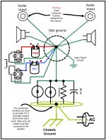
A picture is worth a thousand words...
Here is what I was suggesting.

You may or may not need to break the chassis-connection back at the star-ground (where all of the power supply returns come together).
The RCA-chassis ground keeps the ground loop currents (from the external source) from crawling through your amplifier PCB to get back to chassis.
~ Sam
Here is what I was suggesting.
You may or may not need to break the chassis-connection back at the star-ground (where all of the power supply returns come together).
The RCA-chassis ground keeps the ground loop currents (from the external source) from crawling through your amplifier PCB to get back to chassis.
~ Sam
Hi,
Also you can try the back to back diode to connect the PS ground to hearth ground. It worked for me.
Attached it is a drawing of the start ground showing how to connect the two back to back diode.
Excellent diagram, Tauro. I am just starting a buildup, trying to get my grounding scheme in order. This is good information, another one for the "bag of tricks". Very concise diagram, well done! (although I shouldn't want to connect my PS outputs to ground!
 )
) 
Last edited:
silent (both cable ends again open - disconnected from the source
4. same as 2. (both cable goint out of the chassis, far from power transformer and mains wires) BUT one of them connected to source now. In this case the channel with cable connected to source is humming/buzzing while the second channel with input disconnected from the source is silent as before.
Now you say.
Excellent diagram, Tauro. I am just starting a buildup, trying to get my grounding scheme in order. This is good information, another one for the "bag of tricks". Very concise diagram, well done! (although I shouldn't want to connect my PS outputs to ground!
Just be sure that you use diodes (or a rectifier bridge) that can carry significantly more current than any circuit breaker or fuse that it is likely to be powered through. In a fault condition, if the diodes fail before the building's circuit breaker or fuse does, then you could have an ongoing high risk of electrocution.
And the connections for all of the components in that network should not be connected with solder, since it could melt and disconnect before a circuit breaker or fuse could trip or blow. Bolts or brazing (welding) should be safe-enough.
Last edited:
i also have hum if input is disconnected from dac (dont have volume pot)One more comment - with this new wiring using twisted pair I have also tried to shortcut inputs and it is perfectly silent. By shortcutting input I mean input of the RCA cable (input RCA connector shortcutted --> signal cable ---> output RCA connector connected to RCA jack on the back panel of the amp --> twisted pair of wires --> input terminal on the PCB). Basically it simulates the shortcut on the source of signal including cable between source and amp.
I tried to shortcut one channel while the second channel normally connected to surce. The shortcutted one is perfectly silent while the one that is normally connected to source is buzzing/humming. When I shortcutted the second channel the situation is the same.
- Home
- Amplifiers
- Tubes / Valves
- Hum in tube amp