Hoping to gain some understanding here about differential inputs and ground loop isolation.
I added an opamp based differential input to a powered subwoofer, hoping I could then attach two different systems, which are at opposite ends of the lounge room, and on different mains circuits, without introducing a ground loop.
This clearly didn't work as I'd hoped, because when both systems were wired up, and the volume control on the new input was turned up at all, there was hum.
In the end I rigged an audio transformer, and that did fix the problem. I no longer will need the additional opamps if I go this route.
But I'm hoping someone can advise what's going on and why my ill thought out scheme didn't do the business. I expected common mode noise to be eliminated and no ground loop due to the relatively high input impedances involved.
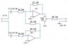
The circuit I used is as pictured, I used an ne5532 and powered it from the existing +-15 rails (with local decoupling of course, not shown) the output goes to the inverting pin of the first opamp in the subwoofer's amp (summing inverting configuration), ground I took from the ground plane near the non inverting pin on that same opamp.
My thoughts: Are the inputs are not sufficiently isolated because of inverting inputs?
Would using buffers make any difference?
Or is a transformer really the only way to truly isolate two systems.
Thanks in advance, any ideas or discussion would be welcome. I know ground loops can be a real frustrating thing sometimes...

The short answer when runnning off different feeds is that an audio transformer really is best as gives galvanic isolation and no current can flow down the shield.
Getting the levels you would need here are possible with opamp circuits but harder.
Links to the Bill Whitlock Papers as ever is a good read and better explained than I ever could 🙂
Getting the levels you would need here are possible with opamp circuits but harder.
Links to the Bill Whitlock Papers as ever is a good read and better explained than I ever could 🙂
Transformer is one of the best and common way to isolate ground loops but not the only. You can use a good optocoupler to do the job, and there exists some of them with two receivers to cancel alinearities in the transfer characteristic.
You need an proper differential amplifier configuration. While transformers do, indeed, perform best on common-mode rejection, a good amount of rejection can be had by a well implemented differential amplifier. Which is not necessarily that easy to realize in practice. It requires extremely tight matching of the resistors. For example, 1% resistors could potentially deliver only 34dB of CMRR. There are, however, some very interesting dedicated differential devices featuring built-in matched resistors for such applications. Such as, the differential line receivers from 'THAT', such as their 1200 series, which feature excellent real world CMRR. Also, there is the similar INA1651 from T.I.
Last edited:
I suspect more accurate resistors are needed, or a preset on one of them, which you tune for maximum common-mode attenuation.
The configuration of that circuit is good in that it has matched input impedances for the + and - input, but is not optimal for noise due to the series resistors on the inputs contributing Johnson noise and (more importantly for BJT opamps) multiplying with the opamps' current noise.
[ Ah ,just spotted it - those caps are way too small in value and can contribute significant common-mode susceptibility at mains frequencies. Either change to something like 10uF or remove them entirely - capacitor tolerances are seldom better than 5% ]
Last edited:
You need an proper differential amplifier configuration. While transformers do, indeed, perform best on common-mode rejection, a good amount of rejection can be had by a well implemented differential amplifier. Which is not necessarily that easy to realize in practice. It requires extremely tight matching of the resistors. For example, 1% resistors could potentially deliver only 34dB of CMRR. There are, however, some very interesting dedicated differential devices featuring built-in matched resistors for such applications. Such as, the differential line receivers from 'THAT', such as their 1200 series, which feature excellent real world CMRR. Also, there is the similar INA1651 from T.I.
THAT THAT Corporation Audio Line Drivers / Receivers Audio Amplifiers | Mouser
Some of these units have laser trimmed resistors for excellent CMRR. Downside is they might be noisy for some applications.
TY-250P Triad Magnetics | Mouser
I heard good things about this series of transformers but haven't used them myself. The popularity of bluetooth DIY projects has created demand for decent quality line level transformers. Ground loop and noise problems can arise when using some of the audio bluetooth boards, apparently.
As far as I know, the well known alternatives to this transformer cost ten times as much.
...differential input to a powered subwoofer, hoping I could then attach two different systems, which are at opposite ends of the lounge room...
Do you realize that, for the general case, you need *two* diff inputs, one from each source? There's two "grounds", which are not at the same potential.
The plan below can be simplified in many cases, but covers the bases.
Attachments
Wow, thanks everyone. Exactly what I was looking for..
Seems I had the basic idea about how the differential "should" work on paper, but some issues with the implementation.
In this case, I will probably go with the transformer, since I know it works 100%, and experiment more with differential inputs another time (with these perspectives taken on board).
I see how this could be true. In this specific case, the amplifier isn't grounded internally, so the system ground will float with one or other input ground. So it doesn't appear to be necessary. Indeed, if I have one or other input attached in practice, there is no hum.Do you realize that, for the general case, you need *two* diff inputs, one from each source? There's two "grounds", which are not at the same potential.
The plan below can be simplified in many cases, but covers the bases.
Which indicates that you are introducing a ground loop the moment both sources are attached and their grounds are connected at the sub (assuming I understand correctly what you were doing).Indeed, if I have one or other input attached in practice, there is no hum.
As PRR pointed out, it takes one balanced input per source to avoid this issue.
I should add also that a transformer on one input solves the hum completely. So a "perfect" CMRR on one of the inputs, seems to do the trick in practice, at least for this specific case.Which indicates that you are introducing a ground loop the moment both sources are attached and their grounds are connected at the sub (assuming I understand correctly what you were doing).
As PRR pointed out, it takes one balanced input per source to avoid this issue.
> one input solves the hum completely
That's why I said "simplified in many cases". If the adjacent gear works together direct, only the far gear needs isolation.
That's why I said "simplified in many cases". If the adjacent gear works together direct, only the far gear needs isolation.
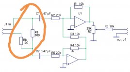
I've been thinking about this, and realised something else I did to ruin the CMRR, at least I think it does.
I forgot this when I drew the earlier diagram. Am I correct in thinking this will cut CMRR in half, along with the signal?
So between this, the caps, and balancing the gain precisely... It should work, I'm thinking. Maybe its worth some persistence.
For context, the source is an LFE driver output, not line. Hence the attenuation.
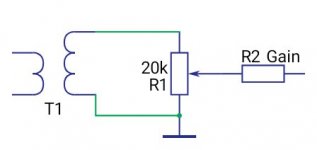
Backup option is a 3 ohm / 7000 ohm transformer. Which is hacked in just now, but the intended configuration is to have the 3 ohm side to the source and the 7000 ohm to a potentiometer and then a suitably sized resistor from wiper to mixing inverting input.


The load resistance must be symmetrical, yes!
100 ohms is very low for balanced audio, it will reduce CMRR simply by bringing differences in wire and contact resistances into significance, as well as overload the drivers at the sending end. 600 ohms is the normal lowest audio load impedance (and many opamps struggle with that).
I'd suggest just change all the 10k to 1k 1%, 20k to 2k 1%, ensure the opamps can drive 500 ohms happily and lose those 100 ohm resistors and input caps.
The load resistance must be symmetrical, yes!
Makes perfect sense... [emoji2357]
100 ohms is very low for balanced audio, it will reduce CMRR simply by bringing differences in wire and contact resistances into significance, as well as overload the drivers at the sending end. 600 ohms is the normal lowest audio load impedance (and many opamps struggle with that).
The source for this is intended to drive a 2 ohm speaker so 100 / 200 ohms shouldn't be a problem. Also the swing may exceed the +-15 rails. It may actually need to see even lower impedance, as I suspect it's a d class amp with an output filter.
I'd suggest just change all the 10k to 1k 1%, 20k to 2k 1%, ensure the opamps can drive 500 ohms happily and lose those 100 ohm resistors and input caps.
I'll have a go and see what happens. For science! Thanks again.
- Status
- Not open for further replies.
- Home
- Source & Line
- Analog Line Level
- Hum / ground loops and differential inputs
