With tube amps having an output transformer I would never have expected switch-on thump to be an issue. Seems I was wrong.
The amps are SE with twin 6S4Ss and Rod Coleman’s DHT Regulator. There’s a 30 second HT delay to allow the regulator to settle down. The OPTs are enormous ElectraPrints and the amps weigh 30kg each.
They sound amazing but were recently connected to some Voxativ full range drivers.
When the HT kicks-in there’s an alarming excursion of the Voxativ cones. It doesn’t help that they’re loaded with a long, open-ended enclosure but with a sealed box the energy would be expended in the voice coil which wouldn’t be good either.
Tying the 6S4S grids to ground and gradually letting them float after the HP is applied might be one solution.
Does anyone have any other suggestions please?
Why the surprise of a thump when you send a voltage/current rush through the transformer to already hot tube cathode ready to rock?
Why the surprise of a thump when you send a voltage/current rush through the transformer to already hot tube cathode ready to rock?
Possibly because I saw it as a sub 1Hz oscillation and even big transformers roll of below 20Hz. Obviously it’s a huge pulse though so however many dB it is down at 1Hz doesn’t matter.
Possibly also because of all the valve amps I’ve built or modified for myself and others I’ve never seen the problem. But none of those had a 30 second HT delay.
Take the delay out.
Unfortunately, that’s a requirement for the DHT Regulator in this configuration with the 2 tubes and single regulator. If the HT is applied too soon one tube hogs the anode current and red-plates.
Attachments
I would recommend Individual Self Bias for the output stage, and for the 2nd stage too.
Failure to individually bias tubes can be a cause of current hogging.
Unfortunately, in order to have Individual self bias on the output tubes, you need 2 each Rod Coleman filament regulators.
But now there will not be current hogging, unless you have one very bad tube, or one very strong tube.
And you can easily see that, by measuring the voltage across the 2 self bias resistors.
You already have 2 RC coupling caps. Use 2 resistor loads on the 2nd stage (nothing to do with the delayed turn on pulse; but makes the circuit better).
Individual self bias resistors and individual plate loads makes the current balance and signal from each triode more equal. And, you can easily see if one of the triodes is way to strong, or way to weak (measure the voltage across the 2 self bias resistors).
Given the circuit you are starting with, the above seems like the easiest and best solution to your problem.
(in my humble opinion)
You did not post a schematic of the power supply. This is a System, not individual pieces that play by themselves.
If you are using a tube rectifier, be sure it is Indirectly heated (with a Cathode, not just a bare filament). A 5AR4 is one example.
That gives some intrinsic delay to the B+
In any case, you should not need a B+ delay.
The large DC pulse created by the delayed B+ transient might magnetize the core (no B+; then Bang! full B+).
It will make woofers 'jump'.
You may have to play music quite loudly to degauss the core (a little like Tape Head Degaussing).
"You should make things as simple as possible, but no simpler" - Albert Einstein.
Last edited:
Take the delay out.
I would recommend Individual Self Bias for the 2nd stage, and for the output stage.
Failure to individually bias tubes can be a cause of current hogging.
Thanks for that. I’ll keep it in mind as a last resort. I’d need another couple of DHT regulators and their associated supplies and there are space issues.
dch53,
Sorry, I was re-editing my post (#7), After you posted.
I added some interesting information.
Sorry, I was re-editing my post (#7), After you posted.
I added some interesting information.
Why do you use mixed bias for 6S4S tubes?
Cathode bias: R13+R14 // C10
Fixed bias: from RV1 tap -voltage- -> R11
When I used mixed bias, exactly separated its, but you linked this two equipment.
Furthermore it realises feedback, because C10 is not ideal capacitor depending of frequency, so on R14 the voltage not pure DC.
Cathode bias: R13+R14 // C10
Fixed bias: from RV1 tap -voltage- -> R11
When I used mixed bias, exactly separated its, but you linked this two equipment.
Furthermore it realises feedback, because C10 is not ideal capacitor depending of frequency, so on R14 the voltage not pure DC.
dch53,
Sorry, I was re-editing my post (#7), After you posted.
I added some interesting information.
Thanks very much for the added detail. Really appreciate it.
The amps have silicon rectifiers. It’s a year since I did the job but as I recall there wasn’t much room for another DTH Regulator and output stage cathode resistors.
My brief was simply to replace the twin 6550 output stage with 6S4Ss. I didn’t need to make any changes to the HT supply.
My brother plays all his music loud so I’m sure the OTs have been thoroughly degaussed!
I kind of regretted taking the job on because I got really fed up with moving the chassis and turning them over. My brother is so impressed with the sound though he may want more converted!
It was my first foray into DHTs which was interesting and integrating the DHT Regulators was also fun.
I think you want to avoid a big positive pulse on the drivers (before C8, C9 charge) when the HT comes up. Maybe you could slow down the HT to this with series resistor or supply the driver stages without the HT delay. Would need to simulate the turn on to see exactly what is happening.
Last edited:
Why do you use mixed bias for 6S4S tubes?
Cathode bias: R13+R14 // C10
Fixed bias: from RV1 tap -voltage- -> R11
When I used mixed bias, exactly separated its, but you linked this two equipment.
Furthermore it realises feedback, because C10 is not ideal capacitor depending of frequency, so on R14 the voltage not pure DC.
That’s a very good question. It’s a year since I did this job but as I recall I did a lot of research on 2A3 amp designs and simply copied the output stage of one that was highly recommended.
I think you want to avoid a big positive pulse on the drivers (before C8, C9 charge) when the HT comes up. Maybe you could slow down the HT to this with series resistor or supply the driver stages without the HT delay. Would need to simulate the turn on to see exactly what is happening.
Thanks. Supplying the driver stages without the HT delay is easily tried and tested safely with a 8R load and oscilloscope.
Simulating the switch-on is great advice too. I usually simulate everything I build but have never bothered simulating switch-on.
Oddly I had to simulate switch off on a PP amp with a similar issue - it sounded like someone had been shot. Again it was the order in which the rails collapsed.
Last edited:
Hard-switching the anode supply is unkind to the amp, and can make it harder to debug other problems.
If you want to gently ramp the amp up into action, I prefer to start with anode voltage ON, but with enough negative grid bias to keep the anode current at zero.
Then, when it's warmed up, the negative bias can be disabled or set to the running-value, with a slow R-C ramp.
you don't need another transformer winding for the bias supply - a cap-coupled rectifier running from the anode-supply's winding can provide enough current for these (temporary) bias purposes.
Hard-switching the anode supply is unkind to the amp, and can make it harder to debug other problems.
If you want to gently ramp the amp up into action, I prefer to start with anode voltage ON, but with enough negative grid bias to keep the anode current at zero.
Then, when it's warmed up, the negative bias can be disabled or set to the running-value, with a slow R-C ramp.
Thanks Rod. This design uses mixed bias on the output stage.
I could simply leave the wiper of RV1 earthed for 30 seconds after switch-on. With a suitable RC there the bias would ramp up after the earth was removed.
Attachments
Last edited:
You miss the opportunity to listen for balanced channel start-up when you delay them. It's a valuable clue to the conditions in each channel. I like to hear both channels come up very close together and within an expected interval for the volume set.
Thanks Rod. This design uses mixed bias on the output stage.
I could simply leave the wiper of RV1 earthed for 30 seconds after switch-on. With a suitable RC there the bias would ramp up after the earth was removed.
It may help - but the ramp up might need to be slower.
Soft-start to eliminate switch-on transient
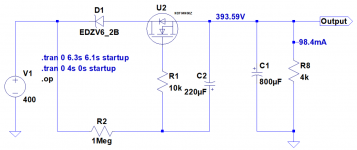
I'm investigatng a soft start to avoid the switch-on thump discussed earlier in this thread.
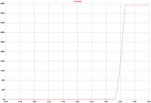
The schematic is shown below with the simulated output. It provides a 3s delay and a rise time of 350ms.
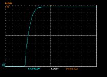
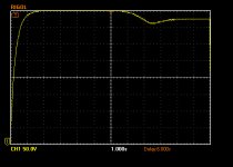
This circuit works similarly to the simulation when preceded by a 30 second delay (3rd image). Location is after the first filter capacitor but before the choke. There's a combined capacitance after the choke of around 800uF.
When used alone (4th image) there's no delay and the rise time is half that in the 3rd image. Why is that?
Background: This need for a soft-start is to fix a problem caused by the fix for a problem resulting from a design decision made a few years ago that I wouldn't make today and discussed earlier in this thread. For a number of reasons I'm unable to fix the original design problem by providing separate cathode biasing and filament heater regulators for each of the output tubes. Main reason is a lack of space in the chassis. Another is that the amps sound great as they are.
I originally purchased K&K Audio's 'excellent HT delay kit to delay the HT by 30s. This fixed the red-plating of one of the parallel output tubes after power-on but introduced the switch-on thump discussed earlier.
So, I recently purchased a couple K&K's Delay and Soft Start kits. These fix the first problem and the switch-on thump.
However, it then occurred to me that since the soft-start provides its own delay of 2s to 3s I could use this to provide both delay and soft-start and use the delay relay to bypass the soft-start circuit (and discharge C2) after the HT has stablised. The 2s to 3s delay might not be sufficient but it's worth a try.
I'm investigatng a soft start to avoid the switch-on thump discussed earlier in this thread.
The schematic is shown below with the simulated output. It provides a 3s delay and a rise time of 350ms.
This circuit works similarly to the simulation when preceded by a 30 second delay (3rd image). Location is after the first filter capacitor but before the choke. There's a combined capacitance after the choke of around 800uF.
When used alone (4th image) there's no delay and the rise time is half that in the 3rd image. Why is that?
Background: This need for a soft-start is to fix a problem caused by the fix for a problem resulting from a design decision made a few years ago that I wouldn't make today and discussed earlier in this thread. For a number of reasons I'm unable to fix the original design problem by providing separate cathode biasing and filament heater regulators for each of the output tubes. Main reason is a lack of space in the chassis. Another is that the amps sound great as they are.
I originally purchased K&K Audio's 'excellent HT delay kit to delay the HT by 30s. This fixed the red-plating of one of the parallel output tubes after power-on but introduced the switch-on thump discussed earlier.
So, I recently purchased a couple K&K's Delay and Soft Start kits. These fix the first problem and the switch-on thump.
However, it then occurred to me that since the soft-start provides its own delay of 2s to 3s I could use this to provide both delay and soft-start and use the delay relay to bypass the soft-start circuit (and discharge C2) after the HT has stablised. The 2s to 3s delay might not be sufficient but it's worth a try.
Attachments
- Home
- Amplifiers
- Tubes / Valves
- HT switch-on thump in DHT SE amp