HT bypass for Rotel RC-995 - noise issue
Hi,
maybe it could be interesting for someone who owns an old preamp and wants to use it within a HT chain.
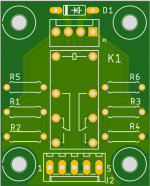
This one has the inputs switched by relays, so it was easy to add a home theater bypass function.

Michael
Hi,
maybe it could be interesting for someone who owns an old preamp and wants to use it within a HT chain.
This one has the inputs switched by relays, so it was easy to add a home theater bypass function.
Michael
Last edited:
Noise problem
Well, maybe someone could help me with a noise issue arised after installing this "feature". I didn't notice it first using headphones, but it's quite hearable, over 20 dB difference! It's mainly noise, not hum or buzz.
Actually, the small device acts as intended. Selecting video input activates the relay, which "removes" the volume pot from the signal path and substitutes it with a voltage divider (24k/4.7k), so the overall gain of the preamp becomes appr. unity.
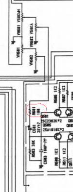
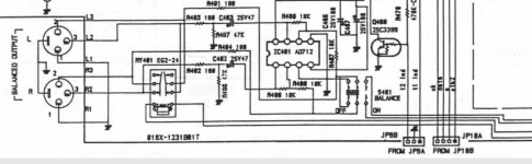
The insertion point of this device is R501 and its brother in another channel. The resistors were removed from the Rotel PCB and are installed on the HT PCB (R5, R6). Rotel used "special" ones, but I used Dale's. Didn't think there should be any noise problem at 100 Ohms.
When another input is selected, the relay connects the volume pot back in.
So the relay basically switches between the wiper of the volume pot and the "wiper" from the voltage divider, fed from the video input.
The input signal (from the video input) is fed through two shielded cables, the shield connected to the signal ground only on one side (Rotel PCB). The original relay for selecting the video input was removed.
The output/volume pot is also connected with shielded cables (two per channel), with shields connected together and connected to ground on the HT PCB and on the Rotel PCB at one point (middle pin of the molex)
The relay supply (+ and -) is connected to the Rotel PCB with hookup wire.
As far as I can see, there is no ground loop, no excessive resistance to produce enough thermal noise, but it's quite noisy. 8 dB difference with video in, over 20 dB with all other inputs, compared to original preamp.
Am I missing something?
Thank you, Michael
Well, maybe someone could help me with a noise issue arised after installing this "feature". I didn't notice it first using headphones, but it's quite hearable, over 20 dB difference! It's mainly noise, not hum or buzz.
Actually, the small device acts as intended. Selecting video input activates the relay, which "removes" the volume pot from the signal path and substitutes it with a voltage divider (24k/4.7k), so the overall gain of the preamp becomes appr. unity.
The insertion point of this device is R501 and its brother in another channel. The resistors were removed from the Rotel PCB and are installed on the HT PCB (R5, R6). Rotel used "special" ones, but I used Dale's. Didn't think there should be any noise problem at 100 Ohms.
When another input is selected, the relay connects the volume pot back in.
So the relay basically switches between the wiper of the volume pot and the "wiper" from the voltage divider, fed from the video input.
The input signal (from the video input) is fed through two shielded cables, the shield connected to the signal ground only on one side (Rotel PCB). The original relay for selecting the video input was removed.
The output/volume pot is also connected with shielded cables (two per channel), with shields connected together and connected to ground on the HT PCB and on the Rotel PCB at one point (middle pin of the molex)
The relay supply (+ and -) is connected to the Rotel PCB with hookup wire.
As far as I can see, there is no ground loop, no excessive resistance to produce enough thermal noise, but it's quite noisy. 8 dB difference with video in, over 20 dB with all other inputs, compared to original preamp.
Am I missing something?
Thank you, Michael
Attachments
Last edited:
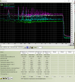
The spectrum looks like you live in a 50Hz landL spikes at 50, 150, 250, 350 etc Hz.
To my eye, your relay is mounted *over* the power supply section. It seems odd the power supply would be so close to the volume control; maybe some clever layout there. Your relay is closer. Unmount your board and try various positions, especially the other side of the volume pot.
To my eye, your relay is mounted *over* the power supply section. It seems odd the power supply would be so close to the volume control; maybe some clever layout there. Your relay is closer. Unmount your board and try various positions, especially the other side of the volume pot.
To my eye, your relay is mounted *over* the power supply section. It seems odd the power supply would be so close to the volume control; maybe some clever layout there. Your relay is closer. Unmount your board and try various positions, especially the other side of the volume pot.
Thank you, I'll try to move the HT board. The other side of the volume pot is occupied (balance pot). At the beginning I wanted to place the board where the original relay for input switching was, but the wires to the volume pot and back would be pretty long.
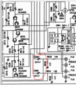
Actually, the position now is not that close to the power supply (attached picture is from the net).

Didn't move the HT PCB, but
- disconnected power from it
- disconnected input/output molex from the HT PCB and put 100 Ohms resistors directly into the connector. Even the last construction didn't change the noise level...


- disconnected power from it
- disconnected input/output molex from the HT PCB and put 100 Ohms resistors directly into the connector. Even the last construction didn't change the noise level...
To me it looks like overall gain may have increased a lot for some reason. What volume pot setting was the unmodified measurement taken at?
Also, your measurement setup needs some work - sample rates are not set up correctly, and it looks like you only have an unbalanced input available, which will require taking care of the resulting inherent ground loop via the cabling. What is the hardware being used?
What's your input full-scale voltage level? -77 dB re: 1 Vrms alone would be ~140 µV worth of noise, an absolutely terrible value for any preamp output. Even in 85 dB / 2.83V / m speakers, that would be 28 dB SPL when followed by a power amp with a gain of 30 (29.5 dB)! For reference, with 88 dB speakers I considered ~270 µV audible and ~500 µV too much, and this would be 4.2 mV.
If you are sure that it's not a gain issue for some reason, I'd change the setup so that the 100 ohm resistors remain in series with the input (at the input) at all times. These are supposed to be near the input to fend off RF and oscillation, and having them at the end of a cable run makes little sense to me.
I still have trouble visualizing the whole mod. A drawing of the whole thing would be nice. The so-so product documentation doesn't make it any easier.
Anyway, the only possible ground loop I spotted is here:
I wouldn't think it should be too much of an issue if cables are kept closely together all the way though. A potential problem is that R501 and R502 are on opposite sides of the volume pot. Where did you connect to ground, J23 or J22 perhaps?The output/volume pot is also connected with shielded cables (two per channel), with shields connected together and connected to ground on the HT PCB and on the Rotel PCB at one point (middle pin of the molex)
To me it looks like overall gain may have increased a lot for some reason. What volume pot setting was the unmodified measurement taken at?
The unmodified measurement was taken about two years ago, so I don't know exactly where the pot was, but the setting should have been about the same like now, about 9 o'clock.
Also, your measurement setup needs some work - sample rates are not set up correctly, and it looks like you only have an unbalanced input available, which will require taking care of the resulting inherent ground loop via the cabling. What is the hardware being used?
Why do you think the sampling rate is not OK? It's 96/24 with all measurements.
I use unbalanced inputs and outputs now, but could use balanced outputs of the pre, since i use them in my setup for connection with the power amp. Will try it tomorrow. The interface is RME Fireface UCX.
What's your input full-scale voltage level? -77 dB re: 1 Vrms alone would be ~140 µV worth of noise, an absolutely terrible value for any preamp output. Even in 85 dB / 2.83V / m speakers, that would be 28 dB SPL when followed by a power amp with a gain of 30 (29.5 dB)! For reference, with 88 dB speakers I considered ~270 µV audible and ~500 µV too much, and this would be 4.2 mV.
I can hear (hardly) the noise in 3 m distance of my 91 dB Speakers and a power amp with a gain of 20. It was almost dead silent before I made the mod.
If you are sure that it's not a gain issue for some reason, I'd change the setup so that the 100 ohm resistors remain in series with the input (at the input) at all times. These are supposed to be near the input to fend off RF and oscillation, and having them at the end of a cable run makes little sense to me.
I'm considering changing the setup so the switching is done after the amp section. Like removing the output caps C507 and C508 and switching either the input from VIDEO IN or the output from the amp section. Could work, but I'm not sure, if the further conversion to balanced output from the maybe a bit high-ish Z video input still will work as intended.
Attachments
Which in turn wouldn't be anywhere near unity gain for the preamp, at least assuming the usual log pot. That's more like unity gain with the power amp included! Probably closer to -40 dB than -16 dB.The unmodified measurement was taken about two years ago, so I don't know exactly where the pot was, but the setting should have been about the same like now, about 9 o'clock.
I have done some calculations on the Rotel's 16 dB amp, which appears to be an adaptation of their power amp circuitry. This is a pretty stupid construction from a noise perspective - they're running the two complementary input pairs at about 1.2 mA per transistor, which generates quite a bit of input current noise (roughly 1.6 pA/√(Hz) from current shot noise alone if we're assuming a beta of ~600), yet the presumably very low voltage noise (can't be much over 2 nV/√(Hz)) is largely wasted because the feedback network is 18k/3k3, not to mention the 50k volume pot with its worst-case 12k5 source impedance. I am guessing they were going for lots of slew rate, but still. This thing would have low enough voltage noise for a decent balanced mic preamp (actually, I think the one in the Behringer Xenyx Q1002USB mixer I have is a bit noisier).
Projected output noise with your 24k/4k7 divider is about 14 µV, up from a little under 8 µV minimum. Now 8 µV is OK but nothing spectacular. The best concepts like this can achieve about 4 µV. Drop R527 from 18k to 5k6 and R526 from 3k3 to 1k, and you should get about 4.5 µV. 3k9 / 680R should drop it below the 4 µV mark. 2k2 / 390R would give little over 3 µV, but not sure whether the added loading is really worth it.
The question is, if you've got a quiet preamp, do you really really want unity gain in HT bypass mode anyway? Your HT preamp may not have noise anywhere near 4 µV. I would suggest dropping levels in bypass mode by another 6 dB or so. So maybe 10k/1k.
With R527 = 3k9, R526 = 680R and a 10k/1k HT bypass divider, I am getting 4.7 µV of output noise. Sounds like a deal. Definitely much better than 14 µV for sure! (Unmodified with 10k/2k, I'm still getting 10.5 µV.)
BTW, I would keep Lch and Rch ground on the HT bypass PCB separate. With your voltage divider in, any common ground return resistance worsens channel separation. Time for The Knife (not the band, nor the implement used by Crocodile Dundee perhaps).
Yet your noise floor drops off a cliff at ~20 kHz. There's only one possible explanation - the ADC actually has to be running at 44.1 kHz and is being upsampled.Why do you think the sampling rate is not OK? It's 96/24 with all measurements.
I have messed with stubborn soundcards with buggy drivers enough to be able to tell when something is not OK. You potentially have to set up I/O formats on up to 3 levels:
1. Application, e.g. RMAA
2. Windows Playback Device & Recording Device Properties
3. Vendor-specific hardware control panel (particularly prevalent among 2000s Creative and Asus Xonar cards)
Oh, fancy! Your results might just as well be from onboard audio though...I use unbalanced inputs and outputs now, but could use balanced outputs of the pre, since i use them in my setup for connection with the power amp. Will try it tomorrow. The interface is RME Fireface UCX.
1. RMAA supports ASIO, as does the RME. I very much suggest you use that. This should eliminate your sample rate issues.
2. Which inputs have you been using, and at what kind of input gain?
OK, that's definitely not >100 µV at preamp output then...I can hear (hardly) the noise in 3 m distance of my 91 dB Speakers and a power amp with a gain of 20. It was almost dead silent before I made the mod.
I think you have quite a bit of input gain dialed in on the UCX for your measurements to look like that.
That's another option, of course.I'm considering changing the setup so the switching is done after the amp section. Like removing the output caps C507 and C508 and switching either the input from VIDEO IN or the output from the amp section. Could work, but I'm not sure, if the further conversion to balanced output from the maybe a bit high-ish Z video input still will work as intended.
Yeah, it looks like source impedance at the video input would increase output impedance on one leg of the balanced out... not ideal.
 Needs a buffer, really.
Last edited:
Which in turn wouldn't be anywhere near unity gain for the preamp, at least assuming the usual log pot. That's more like unity gain with the power amp included! Probably closer to -40 dB than -16 dB.
You are right! I repeated the measurements at unity gain (Volume pot at 12 o'clock and HT bypass seem to give the same (unity) gain) and get much better noise levels. THD doesn't look that good though...
Measurement setup now:
Fireface ASIO 24/96, outputs 3+4 (-3dB) unbalanced into Rotel AUX in or VIDEO in
Rotel unbalanced PRE out into RME front (Mic/Line) inputs (1+2), no gain.
Projected output noise with your 24k/4k7 divider is about 14 µV, up from a little under 8 µV minimum. Now 8 µV is OK but nothing spectacular. The best concepts like this can achieve about 4 µV. Drop R527 from 18k to 5k6 and R526 from 3k3 to 1k, and you should get about 4.5 µV. 3k9 / 680R should drop it below the 4 µV mark. 2k2 / 390R would give little over 3 µV, but not sure whether the added loading is really worth it.
With R527 = 3k9, R526 = 680R and a 10k/1k HT bypass divider, I am getting 4.7 µV of output noise. Sounds like a deal. Definitely much better than 14 µV for sure! (Unmodified with 10k/2k, I'm still getting 10.5 µV.)
If we are talking about changing feedback resistors, I actually would like to reduce the gain of the preamp. I use only "hot" inputs and the 9 o'clock pot position is already way too loud. One volume step on the remote results in to much of adjustment. I hardly can adjust volume halfway precise.
I was thinking about reducing gain, but don't know if the thing remains stable... What do you think about it?
The question is, if you've got a quiet preamp, do you really really want unity gain in HT bypass mode anyway? Your HT preamp may not have noise anywhere near 4 µV. I would suggest dropping levels in bypass mode by another 6 dB or so. So maybe 10k/1k.
I've thought unity gain is what defines the HT bypass? Of course I could go a bit lower and adjust the AV preamp output to go higher, but what would it change?
BTW, I would keep Lch and Rch ground on the HT bypass PCB separate. With your voltage divider in, any common ground return resistance worsens channel separation. Time for The Knife (not the band, nor the implement used by Crocodile Dundee perhaps).
🙂 The HT mod seem to improve the channel separation, somehow. But of course I could cut a bit... The PCB is so tiny, and I even made a SMD version for a small Omron relay...
Oh, fancy! Your results might just as well be from onboard audio though...
1. RMAA supports ASIO, as does the RME. I very much suggest you use that. This should eliminate your sample rate issues.
2. Which inputs have you been using, and at what kind of input gain?
I think you have quite a bit of input gain dialed in on the UCX for your measurements to look like that.
well, I didn't expect that the actual (to low) gain of the preamp and therefore a higher input gain of the RME would affect the measurements such much. But they seem to do so, thank you for the hint.
OK, that's definitely not >100 µV at preamp output then...
The measurements look better now (except for THD). But my impression was clearly more noise compared with the situation before the HT mod.
- more noise in stereo mode (over AUX in or CD in, so not using the voltage divider but the volume pot, relay de energized).
- clearly more noise in HT mode (compared with the AV preamp connected directly to the power amp). Here it sounds to me like some ground loop issues could play a role, but it's mainly not buzz or hum.
Yeah, it looks like source impedance at the video input would increase output impedance on one leg of the balanced out... not ideal.
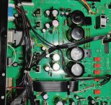
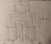
The output of the AV pre looks like this (see attached pic), but I also guess a buffer would be a better way. Wanted to make things simple...


Made another measurement with balanced pre outs. Had to reduce the output of the RME a bit so the volume pot position remained at 12 o'clock.
THD looks better this way...


THD looks better this way...
Massively better, in fact. It is very unusual to see H2 go down by 20 dB for a 6 dB level reduction. All I can imagine is that eitherMade another measurement with balanced pre outs. Had to reduce the output of the RME a bit so the volume pot position remained at 12 o'clock.
THD looks better this way...
a) the RME's balanced input has rather high common-mode distortion or
b) the ground loop is at play somehow.
It would be interesting to see a measurement of the unbalanced out with cabling that actually makes use of the balanced input (i.e. unbal signal --> bal +, unbal ground --> bal -, ignore shield).
Tricky. No explicit compensation in sight, and to be honest I am not sure which stage contributes the dominant pole. Probably either the input stage or the VAS by the looks of it (the OPS is an emitter follower with 180 MHz fT transistors that are run plenty hot), I suspect the former because the current per transistor is the lowest. Would have to simulate the thing to be sure. I don't think it's unity gain stable as-is.If we are talking about changing feedback resistors, I actually would like to reduce the gain of the preamp. I use only "hot" inputs and the 9 o'clock pot position is already way too loud. One volume step on the remote results in to much of adjustment. I hardly can adjust volume halfway precise.
I was thinking about reducing gain, but don't know if the thing remains stable... What do you think about it?
Unfortunately adding a voltage divider ahead of the volume pot is not trivial in this unit either. You might just have to make do with a bunch of external attenuators (12-16 dB or thereabouts). That plus lower-value feedback resistors sounds like a plan to me.
Less noise, especially if the AV preamp output isn't the most low-noise thing in the world.I've thought unity gain is what defines the HT bypass? Of course I could go a bit lower and adjust the AV preamp output to go higher, but what would it change?
For example:
AV preamp output noise - 10 µV (constant in the range we're interested in)
Preamp noise - 7 µV at unity gain, 5.6 µV at -6 dB
Noise at unity gain: 12.2 µV
Noise at -6 dB: 7.5 µV
That's a 4 dB difference after all, and near the threshold of audibility this can be quite significant.
All of this is assuming that noise is the limiting factor, with plenty of amplitude remaining "up top".
The first one is a bit puzzling. It's not like I'd expect your cabling to add hundreds of ohms. Could you measure the total resistance across where the 100R resistors used to be, just to be sure?The measurements look better now (except for THD). But my impression was clearly more noise compared with the situation before the HT mod.
- more noise in stereo mode (over AUX in or CD in, so not using the voltage divider but the volume pot, relay de energized).
- clearly more noise in HT mode (compared with the AV preamp connected directly to the power amp). Here it sounds to me like some ground loop issues could play a role, but it's mainly not buzz or hum.
It might be injected ground noise somewhere, but I fail to see how and where and why.
Last edited:
It would be interesting to see a measurement of the unbalanced out with cabling that actually makes use of the balanced input (i.e. unbal signal --> bal +, unbal ground --> bal -, ignore shield).
I will do these measurements in the next days and will report 🙂
I don't think so either, but maybe a gain reduction from 16 dB to 10 dB could be achievable?I don't think it's unity gain stable as-is.
I will play with an attenuator. Just a divider like 6.8k/3k, or better other absolute values? If we lower feedback resistors, will the input impedance of the preamp also change (original 18k AFAIR)?You might just have to make do with a bunch of external attenuators (12-16 dB or thereabouts). That plus lower-value feedback resistors sounds like a plan to me.
Made a version of HT board with 10k/1k divider. Works fine, measures fine, but I didn't try it in a chain with HT preamp yet 🙂Less noise, especially if the AV preamp output isn't the most low-noise thing in the world.
It's 100 Ohms 🙂The first one is a bit puzzling. It's not like I'd expect your cabling to add hundreds of ohms. Could you measure the total resistance across where the 100R resistors used to be, just to be sure?
I will do these measurements in the next days and will report 🙂
So, here we are.
balanced out -> balanced in
vs.
unbalanced out -> balanced in (Signal Pin 2, GND Pin 3).


- Home
- Source & Line
- Analog Line Level
- HT bypass for Rotel RC-995