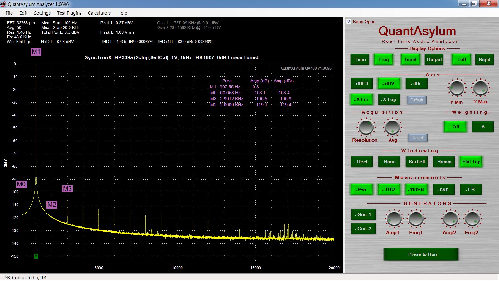
Lost (or gained) 25 dB on 3H
I thought I was going good on the 3H, -132dB
Then, I did this one thing and the 3H, -107dB.
2H, was stable throughout.
When I redid the one thing, I the 3H went back down -132dB.
Any guesses?
I thought I was going good on the 3H, -132dB
Then, I did this one thing and the 3H, -107dB.
2H, was stable throughout.
When I redid the one thing, I the 3H went back down -132dB.
Any guesses?
I thought I was going good on the 3H, -132dB
Then, I did this one thing and the 3H, -107dB.
2H, was stable throughout.
When I redid the one thing, I the 3H went back down -132dB.
Any guesses?
Turning off my Fluke scopemeter caused the 3H to go up about
25dB.
Got something going on with the grounding?
The op amps in the 339a are very edgy. Grounding to some equipment can cause them to oscillate. I had a problem connecting the monitor output of the 339a to an HP3581C. Anytime the ground of the 3581 was connected to the 339a an oscillation was present at the monitor output. Spent two days chasing the oscillation before I realized what was going on.
The op amps in the 339a are very edgy. Grounding to some equipment can cause them to oscillate. I had a problem connecting the monitor output of the 339a to an HP3581C. Anytime the ground of the 3581 was connected to the 339a an oscillation was present at the monitor output. Spent two days chasing the oscillation before I realized what was going on.
Turning off my Fluke scopemeter caused the 3H to go up about
25dB.
Better to remove the probes from circuit rather than just turning off the Fluke and leaving probes connected. The input Z of the Fluke in 'off' mode is not a high Z linear load any more. Same thing can happen with DMM. So, when I am measuring noise and/or distortion, all meter/scope probes are removed.
THx-RNMarsh
Last edited:
@RichEEM,
My bad, it was 64VAC. Sine wave, from A1 TP1 and
TP302, the ground next to one of the power transistors,
designated as the analyzer ground.
Then the HP339a shut down.
@Davada, I did. I'm looking to replace the frequency Venier pot,
I think that is the dual gang with a switch for cal, I'm not sure how
to spec it. I think its 5 MEG, dual gang, but don't know the rest.
it has multiple connections other than just three connections per pot.
Two of the connection are for the switch. Id have to look but there maybe more than one switch.
I checked. There is a DPST switch.
I checked. There is a DPST switch.
Last edited:
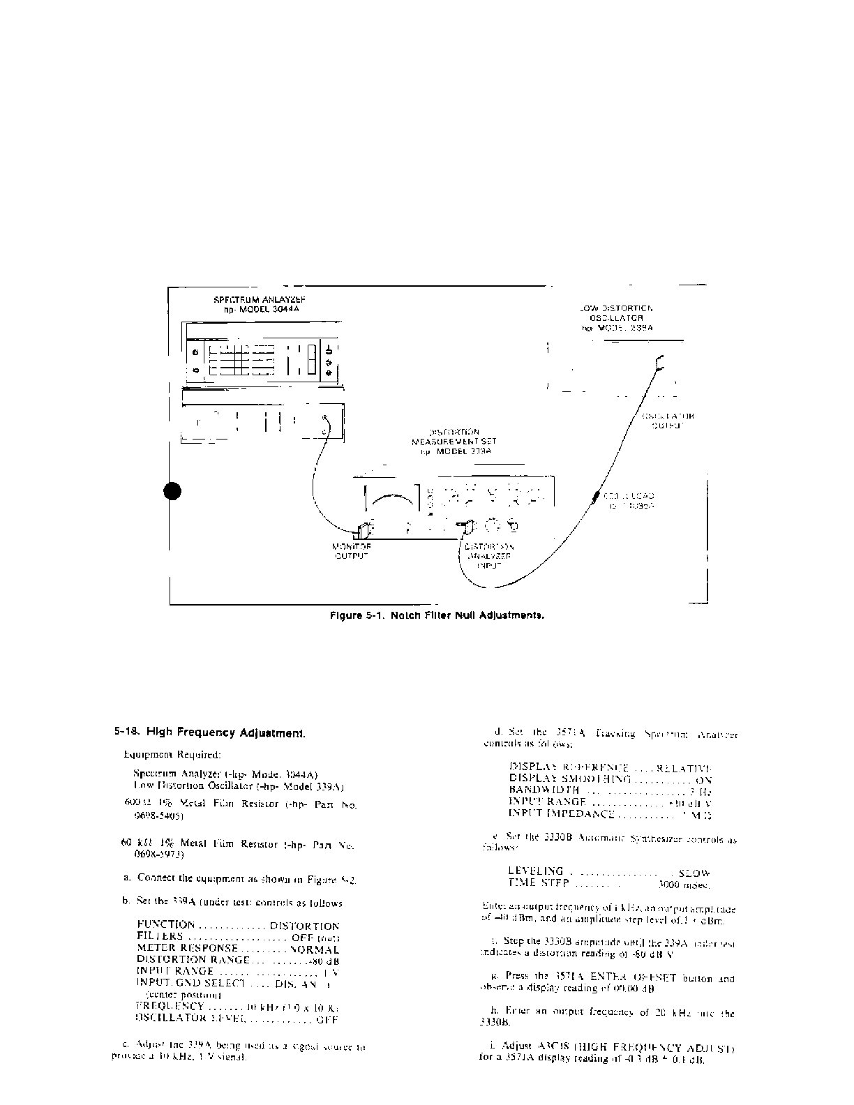
I was trying to do the calibration procedure (cal procs) and had questions as to
how to perform the step/offset procedure when one doesn't
have the equipment listed in the cal procs.
I don't have an HP3571A nor 3044A. Using the QA400 for the 3044A.
Let me post the pages of the Manuel. where it has offsets, and then
I zero it out and I don't have the steps to find me where I'm supposed to be.
So I"ll have to be creative. Wheeee wwwweeeee wwwwweeeeee allll lthe way home.
It will put a smile on my babys face and help her middle ear infection.
Any way where are some the the screen in question.
Somewhere here are the pics I posted but lost.
339A update:
Changed power supply Tants (most of them) to film and foil types.
1 uf changed to stacked films. I have one pair tant left to change
in the PS.
I did some of the easy to access back to back pairs
on the main board. Replaced two with one large
50uf/50V film/foil cap.
Tested it out and getting some HF noise spikes.
Lost 8 dB in H2.
I'm working my way over to the Meter Output, which
is still has low level oscillation. Thinking some of the
spikes is coming from it, when I use the output.
re-reading the Low Distortion thread (selected posts)
so my own notes make sense.
I just hope replacing all these tants will help with lower
THD numbers...ala RNMarsh. I have a small supply of
the film and foils but they are physically large and this
take a bit to fit them in.
Davada noted A1 C47 is important and now
noticed that A1C47 cap that bypassede R50?
was hand selected by HP. it was a 300 PF in there,
not sure if that was right (as I removed everything around
U1 before realizing some needs to remain.
I then replaced C47 it with a padded
micas to 750pf. Not sure what this
accomplishes.
I don't know if this contributes to some of the HF spikes I'm
seeing or I'm worrying over nothings.
I've still got the A1U3 buffer to change to OPA134.
Then, 3 push button filter, quad opamp with the LME49740.
Other misc parts along the way.
For the Opamps around the meter I think U6 and U10.
But not sure whether to use the LT1468 or OPA134
and in which parts.
Coming along slowly and testing as I go.
I do have sony cam pics but keep losing
their 3 inch long special USB adapter.
I'll post as I find things. I want this 339a
to be real good.
Here is the recommenced hook up:


So my reason for asking is how to I work around not having the equipment
to do the offsets? I think I can figure out the first one by turning the Oscillator
output level knob in .1 Hz increments and looking for lowest distortion.
I'm not sure how to perform the offset adjustment in the last instance.
Any suggestions appreciated.
Last edited:
clean contacts and self cal
Here's the latest.
Cleaned the contacts and did a self cal.
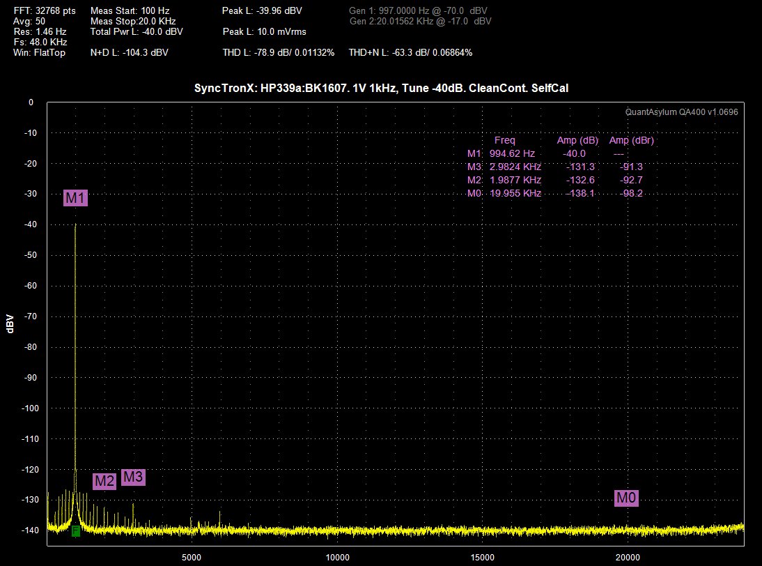
I started at 1V, 1kHz on the QA400, then Distortion Function, tuned notch
to -40dB. So, if I read this correctly and process it correctly from
-78.9dB, I add back (-40dB) [subtract and additional 40dB] leaving
THD figure of -117.98 dB. 12 more dB from cleaning pots/switches
and a self cal.
More changes coming soon.
Here's the latest.
Cleaned the contacts and did a self cal.
I started at 1V, 1kHz on the QA400, then Distortion Function, tuned notch
to -40dB. So, if I read this correctly and process it correctly from
-78.9dB, I add back (-40dB) [subtract and additional 40dB] leaving
THD figure of -117.98 dB. 12 more dB from cleaning pots/switches
and a self cal.
More changes coming soon.
Use the QA400 to look at the monitor output from the 339 auto-nulled to its own oscillator -- no external notch filter. Then adjust the two distortion trim pots for the lowest level of the fundamental -- ignore the harmonics -- you should see the fundamental null out at around -115dB RE 0dB input level.
Now I've gotta go back to tweaking my Frakkintosh -- just upgraded to Yosemite....
Now I've gotta go back to tweaking my Frakkintosh -- just upgraded to Yosemite....
Chem and Distortion
@Richard: 4 Chemicals, 99.99% Isopropal, DeOxit D5, D100, DeOxit MCL100.
Cleaned with Iso/D5/D100 on WoodQtip wrapped with MGChem ELE whipes.
until clean. Then MGChem ELE wipes with MCL Turn switch.
AND
A lot of compressed air.
3 problems, bent 1 little switch part (that I know of) and bent it back,
I fixed it on the switch, twisted it back. Checked, watched. Broke another knob.
Just looking at em breaks 'em.
Now when it is upside down it sounds like arching inside when I touch
the output. Still trying to figure out how to ground it the front panel,
can't find DAVADAs post about it.
@RichEEM, Good luck with your Frankentosh. Does that mean starting over on everything again?
Not sure if I did the calibration right. I ran the oscillator through the
distortion input and out on the monitor.
That for the nulling the Notch Filter, one for Depth and one for Frequency.
I think I go that right. Just wasn't sure how to start and what was with
all that offset stuff, so I just ran through the .1 - .9 on the 339a Frequency
Adjustment.
With the 20 kHz, I shoved the 60Kohm resistor in there and changed
the Capacitance.
I Still have components to replace, but wanted to test along the way so if
problems I know where to look.
Pics at 11.
TWO big to dos:
1. Really need to put TP8 I think via mini coax to AM detector.
2. Fix the noise around the meter and meter moving around,
noise around there. U10 and U6...I think a U4 also.
LT1468s?
or
OPA134s? or some of each?
Last edited:
The offset is a test of how well the auto null is tracking the fundamental. I found if I set the null too deep the tracking was compromised and wouldn't track properly at all frequencies.
Run the frequency up and down a few tens of a Hz. The null should be consistent.
Run the frequency up and down a few tens of a Hz. The null should be consistent.
@Richard: 4 Chemicals, 99.99% Isopropal, DeOxit D5, D100, DeOxit MCL100.
Cleaned with Iso/D5/D100 on WoodQtip wrapped with MGChem ELE whipes.
until clean. Then MGChem ELE wipes with MCL Turn switch.
AND
A lot of compressed air.
3 problems, bent 1 little switch part (that I know of) and bent it back,
I fixed it on the switch, twisted it back. Checked, watched. Broke another knob.
Just looking at em breaks 'em.
Now when it is upside down it sounds like arching inside when I touch
the output. Still trying to figure out how to ground it the front panel,
can't find DAVADAs post about it.
@RichEEM, Good luck with your Frankentosh. Does that mean starting over on everything again?
Not sure if I did the calibration right. I ran the oscillator through the
distortion input and out on the monitor.
That for the nulling the Notch Filter, one for Depth and one for Frequency.
I think I go that right. Just wasn't sure how to start and what was with
all that offset stuff, so I just ran through the .1 - .9 on the 339a Frequency
Adjustment.
With the 20 kHz, I shoved the 60Kohm resistor in there and changed
the Capacitance.
I Still have components to replace, but wanted to test along the way so if
problems I know where to look.
Pics at 11.
TWO big to dos:
1. Really need to put TP8 I think via mini coax to AM detector.
2. Fix the noise around the meter and meter moving around,
noise around there. U10 and U6...I think a U4 also.
LT1468s?
or
OPA134s? or some of each?
If your going to use the am detector BNC change it to an isolated type and take the ground close to you take off point. Otherwise you'll pick all the common mode stuff on the chassis. Keep the ground close to the source.
Pics from 11
Here is the A1 Board so far:
(note the second level adjust pot, the first one broke off)

Here is the power supply with mostly new caps:
1000uf to 4700uf, 47 uf to 10 uf, 1.0uf to 1.0uf.
Ridding the meter of Tants, per RNMarsh.

Here is the giant cap 50uf/50V from 150uf x 2.:

Here is more back to back 47uf tants replaced by 22uf film.

We should all be so lucky to clap our hands
when we put the lid back on things, like bubbles:

Here is the A1 Board so far:
(note the second level adjust pot, the first one broke off)
Here is the power supply with mostly new caps:
1000uf to 4700uf, 47 uf to 10 uf, 1.0uf to 1.0uf.
Ridding the meter of Tants, per RNMarsh.
Here is the giant cap 50uf/50V from 150uf x 2.:
Here is more back to back 47uf tants replaced by 22uf film.
We should all be so lucky to clap our hands
when we put the lid back on things, like bubbles:
- Home
- Design & Build
- Equipment & Tools
- HP339A distortion analyser