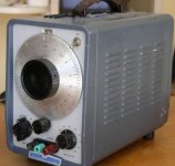
My HP 202C signal generator is acting up, used one for years, now it just oscillates, and can't use it. The sound is what my dad used to call "motor boating".
It has tubes, should I start there?
It has tubes, should I start there?
Attachments
Last edited:
The vacuum tubes are a possible candidate. In the days when every neighborhood drugstore had a tube tester (which was when there WAS such a thing as a neighborhood drugstore), checking tubes was a quick and easy first step.
Given the age of the instrument I'd place wagers on a faulty electrolytic capacitor as the culprit in this case. A dried-out bypass or filter capacitor will have less effective capacitance than necessary to do its job, or a leaky coupling capacitor will upset the biasing of one or more stages.
I haven't looked but I suspect there are several copies of this instrument's schematic, or complete service manual, posted on the 'net. I'd start by checking the voltages in the power supply section. If they seem to be acceptable and not widely jittering I'd look at the voltages on each tube pin in an attempt to determine which stage has the motorboating problem, then focus on the electrolytic capacitors associated with that stage.
Dale
I'll second that --> all the electrolytic caps would be my first thing to replace. Then tubes. After that you'll have it working for a long time again.
-Richard
-Richard
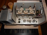
Thanks for the posts. I'm kicking myself for taking a peak inside the other day; talk about bad karma (it was still working then). The tubes looked good and hot; noticed there was not much in there, I did see several caps and they looked easy to replace.
Love the action on them, can sweep very fast (tuned about 200 speakers with it).
I have an extra one, but the dial is almost frozen and very hard to turn.
Thanks again.
Love the action on them, can sweep very fast (tuned about 200 speakers with it).
I have an extra one, but the dial is almost frozen and very hard to turn.
Thanks again.
If you intend to keep this generator in service as a working instrument (rather than ornamentation on the nostalgia shelf, or a "completely stock" museum piece) I'd replace all the electrolytics on principal. Modern capacitors of the same electrical ratings will probably be physically smaller and may require some modifications of any mounting clamps, etc, that may have been used. Pay close attention to the voltage ratings but it's probably OK to use the next larger capacitance value if you can't find an exact replacement value.
I think there's only 4 tubes in that generator, and one of then is a dual rectifier (probably 5Y3 or 6X4). In retrospect it's amazing what circuit designers from a couple generations ago could do with a handful of active devices.
Your frozen tuning dial may be nothing more serious than some congealed lube, either in the dial mechanism or the variable capacitor itself. The repair is conceptually simple - just flush out the old grease with a suitable solvent, and replace it with a dab of silicone grease - but it takes a fair amount of disassembly to get to the parts.
Speaking of nostalgia, I suspect those multi-gang variable capacitors and tuning mechanisms could be used as the basis for a solid-state oscillator with the "look and feel" of the 200 series, but much improved performance.
Dale
Yes thanks Dale, going to need to soon I bet. That would be a job to disassemble the spare, and it probably needs caps also. I did drop small drops of oil at the mini lubrication holes on the gears/shaft and letting it sit.
btw, I'm old to remember the tube-testers in drug stores, etc. - never saw anyone use one.
btw, I'm old to remember the tube-testers in drug stores, etc. - never saw anyone use one.
Before you replace the electrolytics, check the voltage across them first. When this oscillator was made, line voltage really was 110VAC. These days, it's typically 125VAC, which means that all of the voltages inside of the oscillator are substantially higher than design spec. You will probably need to get higher voltage capacitors and this may be one reason they failed. The heater voltages are going to be higher also, but not by much hopefully. I wouldn't trust a selenium rectifier either, if this one has one, so if it was me, I'd replace that also.
I am not familiar with the 202C.
The 200AB used a 5AR4 rectifier and the generator would "wobulate" when the rectifier got weak. The factory rectifier was an Amperex Bugle Boy. The oscillator circuit used 6AU6's and the amplifier used 6K6's.
The 200CD "wide range oscillator" had a solid state rectifier, 6AU6's for the oscillator and 6CW5's for the amplifier. The 6AU6's could cause the oscillator to malfunction, but they would have to be really dead.
We had hundreds of both here when we ran a factory, and they were on 24/7. I was working in the cal lab maintaining them and all the other factory equipment. I don't think I ever changed anything other than tubes in those things.....but that was 30 years ago. The electrolytics might have dried up by now. Some of the really old ones used "bumble bee" caps which are known leakers....but my Fluke 407D still works fine with all its original bumble bee caps.
wobulate...I knew there was word that I was missing.
No lack of voltage at my place - 250v across both bars, 125v each.
No lack of voltage at my place - 250v across both bars, 125v each.
122.9 VAC at my location on a mild spring afternoon, which probably corresponds to a very lightly loaded grid. But the point is very valid. I wouldn't bet on it, but you just might find some taps on the power transformer primary to deal with line voltages above or below the design center value.When this oscillator was made, line voltage really was 110VAC. These days, it's typically 125VAC, which means that all of the voltages inside of the oscillator are substantially higher . . .
Dale
Very interesting that slightly different instruments within the same model series used significantly different tube complements (and presumably different circuits)! I would have expected to see relatively minor tweeks in the passive components.I am not familiar with the 202C.
The 200AB used a . . .
The 200CD "wide range oscillator" had a . . .
Dale
Say for example that the secondary was designed to produce 350 VAC from 110VAC, I think I get that it would produce 398VAC if the line voltage was raised to 125 VAC. I'm not very good at this though...
I do know this is pretty big problem in old tube guitar amps and such audio gear. I assume it's the same with old test equipment.
I do know this is pretty big problem in old tube guitar amps and such audio gear. I assume it's the same with old test equipment.
Had to bring out old scratchy (back up generator) I did oil the bearings a few weeks ago and it works much better, still sounds like something is scraping when turning the dial.
This look the same on the outside, all different inside, smaller tubes, etc. I don't think I can switch any parts. It does seem to be loud and clear as far as tones.
I don't see me rebuilding one of these; how much is a good one?
I see ebay has 100s of them - all sizes.
This look the same on the outside, all different inside, smaller tubes, etc. I don't think I can switch any parts. It does seem to be loud and clear as far as tones.
I don't see me rebuilding one of these; how much is a good one?
I see ebay has 100s of them - all sizes.
Attachments
- Status
- Not open for further replies.
- Home
- Design & Build
- Equipment & Tools
- HP Audio Gen 202C

