Kramtweeter, what's your plan of attack?
Maybe swap 5534s with 49710s and replace a couple key resistors around these opamps with trimpots and adjust those knobs while self measuring to see if you can improve things? Maybe post snip of the schematic here.
i think the notch filter and input amp would be areas of focus.
Cheers
Paba
Maybe swap 5534s with 49710s and replace a couple key resistors around these opamps with trimpots and adjust those knobs while self measuring to see if you can improve things? Maybe post snip of the schematic here.
i think the notch filter and input amp would be areas of focus.
Cheers
Paba
I did a quick review of the 8903 circuit and can make a few observations. Its very similar to the Boonton 1120 (which copied lots of the 8903) so experience there can help. The input noise and the resistor values around the differential to single ended conversion will limit the performance. The 5K resistors need to be smaller. With the LME49710 (as long as you can get a few, they are on the endangered list) you can lower the impedance to more like 500 Ohms. R17 and R105 could be replaced with 1.5W 100 light bulbs. They will be a low value when off and increase in resistance lowering the fault currents when on. This helps lower the noise floor.
The notch filter will be a bigger challenge. Opamp upgrades will help. U5, U6, U11 and U13. The others less impact if any. The multiplier needs tweaking or replacement with a better solution ultimately. Also the Jfets are a potential problem in the tuning as they are not perfect switches and will limit the distortion floor.
In general you will need a really good known distortion free source (Victor Oscillator for example) and a spectrum analyser, Arta for example, to see what is happening. Getting the input board to perform should be pretty straightforward and with opamp upgrades its really going to be the noise that's a limiter.
The filters will be a problem (they all are) and probably a different filter type will be needed. Sallen Key filters are limited by the high common mode in the input.
The analog multiplier is good to a level but has linearity problems, mostly 2nd harmonic.
A reasonable goal would be a residual of .0006%. Going further may run into some design limitations that are hard to overcome. Similar to the Boonton.
For reference: My 8903A hit 0.002 % THD+N at 1 kHz, 1 V RMS, 80 kHz BW. I believe the spec was -80 dB (0.01 %).
I did consider upgrading the bits in the 8903, but ended up taking the plunge on an Audio Precision APx525 instead. #noregrets 🙂
I wonder if you could eek out more performance by combining the 8903 input section with a sound card based analyzer. Just a thought. The sound cards lack a good input section. The 8903 lacks a good analyzer section. Why not combine the two?
Tom
With the LME49710 (as long as you can get a few, they are on the endangered list)
The LME49710 is not on the endangered species list, actually. The DIP and SOIC versions were originally discontinued. The TO-99 version was allowed to live. Then TI did an about face and allowed the LME49710 (and a bunch of others) to live.
For even lower distortion, the OPA1611 is interesting. SMD only, but that's pretty easy to solve with an adapter.
Tom
Kramtweeter, what's your plan of attack?
Maybe swap 5534s with 49710s and replace a couple key resistors around these opamps with trimpots and adjust those knobs while self measuring to see if you can improve things? Maybe post snip of the schematic here.
i think the notch filter and input amp would be areas of focus.
Cheers
Paba
Hi Paba,
My plan of attack is twofold.
1. Find out where that output glitch is coming from and fix it as it may lead to further insights.
2. Study the circuit to see what I'm dealing with and come up with a plan, or abort the mission if it's clearly a no-win situation.
I've done a little bit of #2 and become a little disheartened at the sheer number of op-amps and capacitors in the signal path. I'll start getting serious about this once I've solved problem #1.
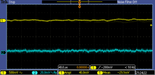
While looking into problem #1, I've come to realise that the entire digital section is a giant noise generator that pervades every aspect of the unit. The amount of power supply noise on the CPU board is astonishing - over 1Vpp in places (see waveform). It's quiet on the motherboard however.
Glitches and noise are also eminating from the latch board outputs too. Of particular concern, there are a lot of control lines going to analog switch IC's which have a lot of noise on them. There's almost no power supply decoupling on the latch board itself.
I've silenced a few of these critical control lines, but it still hasn't eliminated the glitch, so I need to do more investigation. It gets difficult though because the signal levels start to get very small so I can't see what's there.
On the latch and CPU boards I need to get some tantalum capacitors and start adding these in parallel with existing ones to see if any are faulty and need replacing.
So far I've traced the glitch back to amplifier 1 on board 4, the output amplifier/voltmeter assembly. Noise on OU AMP1 was correlated with the glitch, but silencing it by adding a 10n ceramic bypass capacitor at the board entry point hasn't eliminated the problem. So further investigation is needed...
All of this is proving to be rather slow going without a board extender card as I can't easily access most of the test points I need.
Attachments

Hi kramtweeter,
0.002%. Really? I got to get me one of those there things! I thought spec was 0.02% on the 8903.
The LME49710 would be an excellent replacement.
-Chris
Yes it's really 0.002% on my unit, even less if I turn on the 30kHz low pass filter.
On my 8903B, at 1V I get 0.002%, but if you increase the level to 2.5-3V and use the 30 kHz filter, it goes down to about 0.0013%
Hi Conrad,
That's very encouraging news. I should have bought one of these when I had the chance at less expensive units. I was looking for low noise floors, and spec-wise the HP 339A looked pretty good.
-Chris
That's very encouraging news. I should have bought one of these when I had the chance at less expensive units. I was looking for low noise floors, and spec-wise the HP 339A looked pretty good.
-Chris
Many years ago I built the Cordell analyzer and it's been excellent in every regard since. It has the optional tracking filters. The floor is about 0.00015% mid-band at 2V or so. Given that, here are some 1 kHz measurements between instruments I took this morning-
8903B generator feeding Cordell input: 0.0006% @ 1V, 0.0005% @ 3V.
Cordell generator feeding 8903B input: 0.0015% @ 1V with 80 kHz filter, 0.0012% with 30 kHz filter, 0.0010% @ 3V with 80 kHz filter, 0.0009% with 30 kHz filter.
8903B generator feeding HP334A: 0.012% @ 1V, no hipass, 0.008% @ 3-5V, no hipass.
It took me a few minutes to remember how to work the old 334A, and I haven't checked the cal recently, but it should be typical of what they can do. No doubt things are more complex than they appear on the surface, but these numbers should at least offer a clue as to what you can expect from the various units. IMO, the 8903B is well balanced in its design and getting more performance out of it might require attention to just about every part of it. I wrote some buggy software for the Prologix adapter and with that it's an extremely fast and convenient unit for most applications. Without automation it's a bit of a PITA. No doubt Pete's software is better, but I don't think it's compatible with my GPIB adapter.
Last edited:
Hi Conrad,
That certainly puts some perspective on things. Thank you.
I have a couple sound cards, an HP 339A, HP 334A and an HP654A (out on loan). I have to set up the super low distortion sine wave generators based on the Linear Technology app note. Right now, my work is often below the noise floor of the HP 339A, so I will be doing the modifications to it in hopes of at least seeing what's going on down there. I also do have an HP 35665A FFT unit and an old 3580A too. I love restoring test equipment, and if I can use it, so much the better!
-Chris
Hi kramtweeter,
I'm familiar with how HP does power supplies. They are okay, but not spectacular. I don't know how much better performance you can get, but I do know that you can't chase 20 to 40 dB of improvements without cleaning up the power.
-Chris
Hi Chris,
Well after troubleshooting my problem #1 a bit more tonight I've come to the conclusion that the microprocessor/latch boards are injecting digital noise into the +/-15V analog op-amp power supplies. These noisy supplies are then being fed to the sensitive analog boards and being amplified. I believe this is causing the negative going glitch noise I see on the monitor output.
So in summary, I think you're 100% correct! The first place to start is to try to clean up the unit's power supply.
The first thing I'm going to attempt is to try to suppress as much noise at source as possible. Namely on the microprocessor board which is noisy as hell!
For this job I'm going to order some 100n axial ceramic capacitors and some axial tantalum's too.
If anyone else has any 8903A power supply cleanup suggestions, I'm all ears...
Hi kramtweeter,
Try to quiet that board down, then consider making a power supply for the digital section and keep it separate from the analog section. Running the analog supply through shielded wire to the analog circuits can really help, or experiment with how the wire is run.
Of course, you could always make a much better power supply and use that for the analog section. The big plus is that the heat generated by the regulators will be reduced. The load is split now.
-Chris
Hi Demian,
that analysis and info is very generous and helpful. I can probably do some but not all inside my skill set and tool set. But I guess we should all certainly start with those suggestions.
Hi Conrad,
very helpful too even if it is the B and not the 8903A. I think it confirms then the input amp block is a bottleneck and possibly the notch and analyzer side and the 8903B source is probably fine. Which many have already suspected.
cheers
paba
Anyone want a pair of 8903s?? Probably both "B" but maybe one was an "A".
Neither in perfect working condition... parked on the shelves for too long.
Went another direction when a VP2275A dropped in my lap.
PM me, "let's make a deal"!! 😀
(I know this is not the For Sale section... but...)
_-_-
Neither in perfect working condition... parked on the shelves for too long.
Went another direction when a VP2275A dropped in my lap.
PM me, "let's make a deal"!! 😀
(I know this is not the For Sale section... but...)
_-_-
The cause of the glitch on the output is the high dv/dt ramp-gate signal on A4 leaking into the nearby amplifier stages, and also back out to the input board where it's being re-amplified.
This glitch occurs at the end of the measurement period, so it's not going to affect the THD readings, but I still don't like having it on the monitor output.
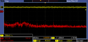
I've made a few mods to A4 to minimize it, but it can't be eliminated entirely on the 80kHz setting because the 80kHz mux is physically too close to the ramp-gate circuits and there are noisy tracks running nearby.
The picture is much rosier with the 30kHz LPF on, the glitch is pretty much gone now. The yellow trace is monitor output, the blue trace is A4 TP6.
This glitch occurs at the end of the measurement period, so it's not going to affect the THD readings, but I still don't like having it on the monitor output.
I've made a few mods to A4 to minimize it, but it can't be eliminated entirely on the 80kHz setting because the 80kHz mux is physically too close to the ramp-gate circuits and there are noisy tracks running nearby.
The picture is much rosier with the 30kHz LPF on, the glitch is pretty much gone now. The yellow trace is monitor output, the blue trace is A4 TP6.
Attachments

Just for reference, here are some steady-state power supply current consumption figures measured across the fuses at the back of the unit:
+5V - 2A (turn on surge 5A)
-15V - 370mA
+15V and +12V - 410mA
+5V - 2A (turn on surge 5A)
-15V - 370mA
+15V and +12V - 410mA
Did any of these mod's get done?
I'm going to try and restore my 8903a and could use some help/tips on what to replace or modify?
Going to start on the oscillator board A5, going to replace the capacitors on there, are there any opamp upgrades that could be done to this board whilst its out?
Thanks
Chris
I'm going to try and restore my 8903a and could use some help/tips on what to replace or modify?
Going to start on the oscillator board A5, going to replace the capacitors on there, are there any opamp upgrades that could be done to this board whilst its out?
Thanks
Chris
- Status
- Not open for further replies.
- Home
- Design & Build
- Equipment & Tools
- HP 8903A Audio Analyzer Mods and Upgrades