Assuming the power rails are OK :
(1) Take a look at the signal at R44, the input to the balanced amp. It should be 3v peak to peak and a perfect sinewave. Probe both ends - they should be near identical. if this is OK then the problem is in the balanced amp
(2) Check the bias point (voltage) at emitter/collector for Q13/14 Q15/16 against the figures in the schematic. Check the voltage accross R64 (should be ~11.8v and nearly dc) this provides the tail current for the Q15/16 diff-amp but is modulated by the DC balance R74/75 and C32 at higher frequencies.
(3) check the signal at the O/P R76/77. if this is very asymetric it will pull the tail current for Q15/16 out of whack - you can disable this by unsoldering Q22 base and connecting it to 0v to ease diagnosis.
PS, thx for the schematic !
dave
You can replace the tant caps with ordinary electolytic caps. this is probably better anyway as tant caps have a rather nasty failure mode. Do this before you investigate further ...
AFAIK, tant has only small size in its favor ...
AFAIK, tant has only small size in its favor ...
I have been having a terrible time finding a 180uF 10v (or any voltage) axial lead capacitor, aluminum or tant.
what do you guys think about using two capacitors in the place of one? I dont like that idea at all...
i dont know what else to do. i can only get the correct sprague caps in lots of like...35...and 16 dollars a piece.....eh, I could get an HP 339A and be done with it
DRC What do you mean by nasty failure mode?
(oh, does anyone have a service manual for a heathkit IM 12 harmonic distortion analyzer??)
once I get that capacitor in there...them the real diagnostics and troubleshooting begin
Yopu know that C40? the 180uF? Well, where is it in the schematic because the schematic you posted is not the section you are referring to for this capacitor. I am thinking you could possibly substitute the value for maybe, 160uF or 200 uF. But I need to know the function of that cap. By the way you can check mouser, I'd rather buy there, they have more oddball components. And if that doesn't work then try Jameco, or maybe Newark.
Color test.tomato, does it work?
Color test.tomato, does it work?
yea, that schematic was posted by DRC. I bought the whole manual on pdf, great resolution too, if you would like a copy Ill just email it to you, or tell me how to post it on here.
Ill try to upload the schematic of where C40 is. I am not sure if this capacitor is what is making the output be only half a sine wave and no movement on the meter...but we will see. I think its one of the transistors in the balanced amp.
i havent tried newark yet. but everyone else has min order of at least 25 at 16 a pop. bleh.
your tomato looks great by the way
Attachments
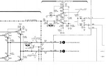
thanks for your quick reply, I might as well reply as soon as I can also. you know that 180uF (thanks for the schematic picture) well if ti's busted then the signal will not come through the average detector, which I believe is responsible for the accurate level tracking, an AGC circuit in some sorts. Can anyone else confirm? Or am I in the potatoes?
Anyway, if you take a 160uF or a 200uF (remember these components have tolerances) it will be OK. As you can guess its only function is to eliminate the DC component from the signal coming out of Q25, so as to have 0volts going to the two rectifiers. clever, if complicated arrangement for a DC tracker.
You know you might as well check what signal you have on the collector of Q25, my guess is it should be a sinewave, if it's not then, you have a problem for earlier up on the line, possibly what's feeding the average detector, the Final amplifier.check to see if
-R70, R71, are open circuit
-C31 is shorted (that would short one rail of the power supply)
Note that what I just said is for the top side, check the lower side (the PNP side of the amplifier).
I'm not trying to sound like a smart a$$ I just say what I would do. Hope it helps!
woah gainwire! I totally forgot about tolerances! gees... a 200uF with 10% tolerance overlaps the 180uF 20% needed..
okay, I'm off to the electronics store tommorow ( I really wish someone had an all night electronics store. like..join up with 7 11 or something. haha)
I know that my power rails are in great shape. +31.0 v and -26.0 v dead on (thankful)
I wish the service manual showed what the waveform looks like when it goes through the balanced amp, because then I could verify what I am seeing on the scope is what is intended.
Once I put that cap back in (Ill do it tomorrow) Ill take some pictures of what the waveforms look like at various points in the balanced amp. hey, and gainwire, if you want the service manual for the 654A, just email me, or give me ur email. It's actually a nice pdf. great schematics
thanks again for your interest!
(the schooling I am doing right now is still at DC circuits. what a bore. haha. I guess you have to start somewhere. It will be over a year until I start doing new material for me. yawn...)
yup, tolerances are one thing that can work in your favor when you can't get the right value, honestly that's the only time I think about them! Unless I'd be building a DAC r-2r ladder.
Anyway, as you say, waveforms would be helpful. I am actually surprised HP did not do this as I have a couple of HP manuals from the seventies and they do include waveforms at different testpoints. Oh well. HP kicks butt anyway!
So wait a sec here, you have two power rails, and they are not equal? That's weird. If you dont' mind I'll take kyou up on the offer... pdf please how big is the file?
Unless you've posted it on BAMA.
Oh, one thing, you'd be best off to test which way the tolerance goes, if it does go (and I am sure it will) up or down... you want the 200uF cap to go down, but check it with a multimeter, if your meter has that function. Or ask the store to check them while you're there. Jeez I always feel like I'm writing a chapter in freakin' book!
by the way I know what it feels like to be ahead of the game, the same situation happened to me in College, I knew the colour codes, part numbers, manufacturers, schematics symbols since I was like 14 yrs old. It's a good situation in which to be...
gain-wire

You're getting closer
Hi again deyjavont,
Well you're going to have to post the part of the schematic where you find Q11, because it's kind of hard to tell why you get those signals on its pins, without knowing what's connected to it. I mean it could be the emitter resistor (if Q11 serves as a common emitter or emitter follower amplifier) of Q11 is bad, it could be that Q11 is bad, it could because the voltage supplying that part of the circuit is not correct because of some other component no so far away.. You know?
So post that part of the schematic, and we shall investigate further...m'yes.
One thing that's common in debugging, you might know about it, is going to the last known good point. I think that's porobably what you're doing, by showing us those three scope pictures. Is supect you are on the right track. Keep me posted, I got nothin better to do than play guitar and debug circuits. Oddly enough I can't find a job doing specifically that!
cheers,
gain-wire
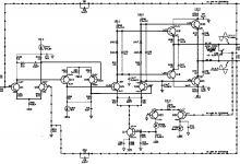
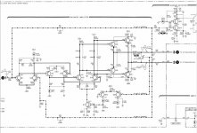
DRC posted a fuzzy version of the schematic I am posting. Q11 is to the far left in the middle. it is the first transistor in the balanced amplfier. the buffer amp is what precedes it.
I am a little hazy on my knowledge of balanced amps, and how you split up the signal to have the two signals 180 degrees out of phase. ( or are they just inverted?)
My circuit analysis professor suggested I should replace all the capacitors in the balanced amp, considering the unit is from 1968. But he didnt know what that waveform means. haha.
gain-wire, you should work for ZVex to have your perfect job. haha. I play guitar as well, but I sold it a little bit ago (well..both of them, a les paul and a tele) and I just havent had the money or time to get another one ( I am really picky when it comes to guitars. I still have my half stack and all my effects, could never get rid of those!
After I fix this oscillator I have a few other things to fix. A rackmount delay unit, a distortion analyzer, a 60's Crown power amp. haha.
but the thing I am eventually heading towards making is a tube based tape delay unit. Something inexpensive (unlike fulltone) and sounds good.
Im still working on the high freq bias oscillator and the transport of the tape. I have like..a dozen reel to reels that I canibalize for parts. haha
I love delay. And guitar too.
happy thanksgiving!
-chris
Attachments
Hi chris, a 220u should be OK for C40 as it appears to only isolate the DC signal component. If it would fit, i would go for 35v given the supply rails are at 31V. Under normal operating conditions this would be un-nessesary but for an extra few cents its not so unreasonable ...
I'm a bit confused about the waveform posts ...
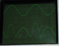
Post 30 - 2 traces : is this the base and collector of Q11 ? If so it looks fine ...
Post 31 - 2 traces : not sure what these are, maybe Q12 ? If so, looks like some crazy compensation going on but looks OK, ie a fault somewhere else causing this - ** possibly **
Post 32 - 2 traces ; again i'm confused, is the lower one the output ?
OT, just back from 3 weeks in the USA so i'm a bit lagged
I'm a bit confused about the waveform posts ...
Post 30 - 2 traces : is this the base and collector of Q11 ? If so it looks fine ...
Post 31 - 2 traces : not sure what these are, maybe Q12 ? If so, looks like some crazy compensation going on but looks OK, ie a fault somewhere else causing this - ** possibly **
Post 32 - 2 traces ; again i'm confused, is the lower one the output ?
OT, just back from 3 weeks in the USA so i'm a bit lagged
Here's how i would invesigate the output amplifier, 1st stage :
(1) Connect CH1,CH2 probes the Q11 and Q12 collectors, with the same channel gain and DC coupled, indicating where the 0V point is. This will show the DC bias conditions. The schematic shows the nominal values ...
(2) Switch to AC coupling (adjusting gain on both channels). This will show the dynamic signal at each collector, each may look somewhat distorted but this is OK ...
(3) Switch to "difference mode". The difference signal should not look distorted ...
repeat for Q13/Q14 and Q15/Q16
my guess is that at some point one of the collectors will be missing OR the fault is in one of the OP buffers Q18,19,20,21
Chris,
Without any expertise on these particular things (so take all this for what it may be worth), it looks to me like Q11 looks unhappy because it maybe isn't getting any negative feedback. NFB is supposed to be coming in by way of Q12, making it go ugly and not follow the whole waveform.
So what is the AC signal at the base of Q12? It should look pretty much identical to that at Q11's base since it is the global NFB feed point. If not, look down the line at the collectors of the other gain stages (Q13&Q14; Q15&Q16) to see if the signal suddenly gets lost somewhere down that chain.
What is at the emiiters of Q20&Q21 (they should look about the same)? Those are where the NFB to Q12 comes from.
yup, I agree with that reasoning, although I didn't explain it to him as simply as that!
anybody here interested in buying a some Nice Tek 543A type plugins? I have a type M plug-in unit and a type CA vertical amplifier. Both have original tubes and were functional the last time they were used.
anybody here interested in buying a some Nice Tek 543A type plugins? I have a type M plug-in unit and a type CA vertical amplifier. Both have original tubes and were functional the last time they were used.
okay guys. sorry for the lack of replies, been soo busy with midterms and lab reports!
Ill attach photos of what is happening in the circuit and i will try to be as specific as possible. I am almost thinking that it might just be a bias problem, but we will see. I suspect that Q11 is bad, biased wrong, or something totally different.
thanks again, if you are still with me...
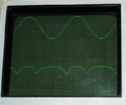
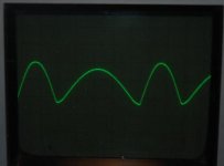
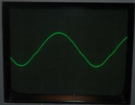
this picture is of Q11 Collector.
Q13 base, Q13 collector and Q14 emitter are the same as this (or same waveform)
Ill attach photos of what is happening in the circuit and i will try to be as specific as possible. I am almost thinking that it might just be a bias problem, but we will see. I suspect that Q11 is bad, biased wrong, or something totally different.
thanks again, if you are still with me...
this picture is of Q11 Collector.
Q13 base, Q13 collector and Q14 emitter are the same as this (or same waveform)
Attachments
- Status
- Not open for further replies.
- Home
- Design & Build
- Equipment & Tools
- hp 654a test oscillator