So i picked up this 403B meter and the Battery in it is shot, Instead of replacing it would a string of 6.5v Zener diodes work as a bypass? i have no need of operating it on batteries and no urge to spend $60 on batteries. Is there another cheap way of bypassing the batteries?
The battery is a series string of four 6.5 volt nicads, centertap ground with +13v, -13V, and -6.5V taps. Suggestions since the meter will not seem to work unless the batteries have enough charge.
Couldn't you build the required supplies using LM317/LM337's .
You need three supplies + / - 13.5 V and -6.5 V . It appears to be a simple straight forward solution . Am I missing something ? 😕
You need three supplies + / - 13.5 V and -6.5 V . It appears to be a simple straight forward solution . Am I missing something ? 😕
Prolly not but i'm still trying to teach myself most of this stuff and i haven't dealt with the voltage regulators yet.
OK, sorry about that. The circuit would be a straight forward application of whats recommended in the application manual. I can't put that up now. Maybe tomorrow morning as it's time for me to go to bed now ! Meantime someone would have had time to put one up for you.
I checked your meter casing. It might take a board on the top ( inside the case) or you can attach the assembly to the rear of the meter itself on the outside ! You can mull over this till I see what others have suggested tomorrow !
I checked your meter casing. It might take a board on the top ( inside the case) or you can attach the assembly to the rear of the meter itself on the outside ! You can mull over this till I see what others have suggested tomorrow !
Awesome! sounds good, thank you. i may be able to fit a small board inside the case where the batteries are now.
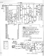
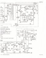
The 403B Transformer isn't center tapped, and the HP403B power supply actually produces 3 voltages, +/-13V and -6.5V, and a ground reference you'll need, a schematic is shown below.
You can use a BUF634 to derive an artificial ground, and the 3 voltages a la:
The resistor values for the LMXXXL regulators are comparatively high -- this helps the bypass capacitor knock down noise.
I came upon this as I am replacing the diode rectifier circuit of my 403B with a true rms detector.
An externally hosted image should be here but it was not working when we last tested it.
You can use a BUF634 to derive an artificial ground, and the 3 voltages a la:
An externally hosted image should be here but it was not working when we last tested it.
The resistor values for the LMXXXL regulators are comparatively high -- this helps the bypass capacitor knock down noise.
I came upon this as I am replacing the diode rectifier circuit of my 403B with a true rms detector.
Last edited:
I've solved this problem in similar test equipment by just replacing the batteries with a big electrolytic, bypassed with a suitably rated zener diode to match the original battery voltage. Just measure to be sure you know what the charging and operating currents are.
I got these from a battery supplier who had 23 in stock, and they were discontinuing the line. No solder tabs.
The energy density of a Lithium Ion battery pack would be much higher -- or you could just use "AA"s and 2x the 8-AA holder from Radio Shack.
The energy density of a Lithium Ion battery pack would be much higher -- or you could just use "AA"s and 2x the 8-AA holder from Radio Shack.
An externally hosted image should be here but it was not working when we last tested it.
The original battery last for a couple decades. I just bought a new mfr'ed replacement for it. Wont need to change it ever again; not in my life time. And, if I do, I'll be grateful for living so long.
Thx-RNMarsh
Thx-RNMarsh
I got these from a battery supplier who had 23 in stock, and they were discontinuing the line. No solder tabs.
The energy density of a Lithium Ion battery pack would be much higher -- or you could just use "AA"s and 2x the 8-AA holder from Radio Shack.
An externally hosted image should be here but it was not working when we last tested it.
😎🙂
Hi,
Has anyone got the circuits that where linked in this post? The links no longer work. I want to replace the Batteries in my HP-403B with voltage regulators, and need some ideas of how it has been done previously.
thanks and regards,
JEFF
Has anyone got the circuits that where linked in this post? The links no longer work. I want to replace the Batteries in my HP-403B with voltage regulators, and need some ideas of how it has been done previously.
thanks and regards,
JEFF
The 403B Transformer isn't center tapped, and the HP403B power supply actually produces 3 voltages, +/-13V and -6.5V, and a ground reference you'll need, a schematic is shown below.
An externally hosted image should be here but it was not working when we last tested it.
You can use a BUF634 to derive an artificial ground, and the 3 voltages a la:
An externally hosted image should be here but it was not working when we last tested it.
The resistor values for the LMXXXL regulators are comparatively high -- this helps the bypass capacitor knock down noise.
Thanks for the circuits of the unit. Do you have the voltage regulator modifications mentioned?
regards,
JEFF
regards,
JEFF
> I want to replace the Batteries in my HP-403B with voltage regulators
If you are abandoning battery operation, you just need four gizmos that will hold about 6.5V when fed with current. Zener diodes. The part I found, 1N4736A, is 23 cents each at Mouser; 6.5V (+/-0.3V) 1/2W Zeners are cheap.
If you are abandoning battery operation, you just need four gizmos that will hold about 6.5V when fed with current. Zener diodes. The part I found, 1N4736A, is 23 cents each at Mouser; 6.5V (+/-0.3V) 1/2W Zeners are cheap.
Attachments

Last edited:
Thanks. I did initially consider zeners, but thought they would change voltage slightly due to mains voltage variations and this would cause slight alteration of the unit's circuit balance when set to high sensitivity. I thought the line regulation of Voltage regulators would be much better.
> they would change voltage slightly
So would the batteries. Probably more than Zeners on a wall-outlet.
Yes, at my 125V-108V house (long wires), I'd check this theory. But most houses don't sag near this much.
So would the batteries. Probably more than Zeners on a wall-outlet.
Yes, at my 125V-108V house (long wires), I'd check this theory. But most houses don't sag near this much.
I think that I should scan my manual and send it to Keysight. Their copy whizzed by the microfiche and is unuseable.
As mentioned, this is a great device but early 1960's with poz feedback to achieve high input impedance. Only a few years later they figured out how to do the same thing with the devices of the era.
If you rely on the 120VAC supply you aren't going to be happy with the very low volt readings. It;s less mind-bending to just make up a new battery pack from some lithium ion cells.
- Status
- Not open for further replies.
- Home
- Design & Build
- Equipment & Tools
- HP 403B Volt / dB meter problem