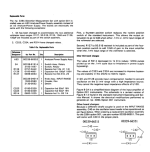
This is just a post for stitched together schematics, separate parts list (still NOT higher resolution than you've probably already seen), and separate manual changes.
Innards of my 339A
Big/origin mods and greening thread - Low Distortion Audio Oscillator - Page 46 - (Post #901)
One more - HP 339A Distortion Analyser
Mods & Upgrades Summary post by SyncTronX
About Total Harmonic Distortion Analyzers - Dick Moore (RIP)
The IG-339A oscillator, an HP 339A oscillator in new old clothing - Dick Moore (RIP)
HP Manuals
(I recently obtained one but doesn't power on, so will be starting there before any mods🙂
Now updated with all manual changes.
Orange indicates components value changed.
Green indicates newly added component(s).
Some components also removed from schematics.
Innards of my 339A
Big/origin mods and greening thread - Low Distortion Audio Oscillator - Page 46 - (Post #901)
One more - HP 339A Distortion Analyser
Mods & Upgrades Summary post by SyncTronX
About Total Harmonic Distortion Analyzers - Dick Moore (RIP)
The IG-339A oscillator, an HP 339A oscillator in new old clothing - Dick Moore (RIP)
HP Manuals
(I recently obtained one but doesn't power on, so will be starting there before any mods🙂
Attachments
Last edited:
Anyone out there add Option 001 to their 339A's themselves?
Based on this info, with a prefix 2025, mine was made week 25 of 1980.
Pics from the innards of my 399A.The HP 339A ....with option 001 installed used an A53/Power Supply assembly instead of
an A3 Analyzer/Power Supply. The boards are electrically the same with the following exceptions:
Based on this info, with a prefix 2025, mine was made week 25 of 1980.
Attachments
Words of advice: get the analyzer working to original spec before attempting any of the upgrades you'll find here in the forum. I'm not denigrating any of these efforts, just recommending you start from a working instrument and introduce improvements systematically, one at a time.
Good luck, enjoy!
Steve
Good luck, enjoy!
Steve

Oh come on Steve, what fun is that? The challenge of changing everything, upgrading, modifying, etc
and THEN
we find out it doesn't work...
Which was (were) the (one) piece(s) that was causing the original issue.
Now, where to begin to trouble shoot?
Undo all the upgrades, modifying, etc.
Get back to original unworking condition again.
Oh, which parts did I throw away, was I too efficient with their disposal?
Did the trash man comeith and takeith away? He just came, can I hunt
him down for that unobtainium part I didn't know was discontinued two
decades ago that was special "qualified' order.
What do you mean you emptied your truck at the transfer station?
It's already off to the land fill is it near by? Another city, which state?
Oh its on the transfer barge.
PITA
Now what do I do?
Cheers,
Words to abide by methinks.Words of advice: get the analyzer working to original spec before attempting any of the upgrades you'll find here in the forum. I'm not denigrating any of these efforts, just recommending you start from a working instrument and introduce improvements systematically, one at a time.
Good luck, enjoy!
Steve
Updated the schematics to include all manual changes, included some notes.
I saw that Fig 8-13, F100: fuse value was changed from 0.62A to 0.1A for serial numbers 1730A02436 and up.
I saw that Fig 8-13, F100: fuse value was changed from 0.62A to 0.1A for serial numbers 1730A02436 and up.
I pulled my fuse (F100) and it is indeed a 100mA not 62mA. But my serial number is after all manual changes. The 100mA seems blown as I start to troubleshoot my 339A.
This is interesting, on the back of my A2 board, one of the posts seems to be soldered to the pcb:

Question for anyone out there, on the oscillator board, I've seen three different trim pot replacement values for the AR51 (2k ohm 1% 1/8W resistor) including a 5k pot shown in RNMarsh's post (picture shows trim pot with 502 markings-> 5k ohm). As well as 2k (same as original resistor value) and also 10k ohm trim pot. Any reason to use a trimpot value other than 2k for R51?

This is interesting, on the back of my A2 board, one of the posts seems to be soldered to the pcb:
Question for anyone out there, on the oscillator board, I've seen three different trim pot replacement values for the AR51 (2k ohm 1% 1/8W resistor) including a 5k pot shown in RNMarsh's post (picture shows trim pot with 502 markings-> 5k ohm). As well as 2k (same as original resistor value) and also 10k ohm trim pot. Any reason to use a trimpot value other than 2k for R51?
Two blown fuses,
the chassis F2 osc level pot inline mini fuse,
62mA, 250V, Fast-Blow, .281 x .093" (mini/pico fuse)
and the A3 board (F100) cartridge fuse,
100mA, 250V, Norm-Blow, 1.25 x .25" are blown.
The A2 board (F1) cartridge fuse is the only good one (along with the .250A mains fuse, as the unit does power on).
62mA, 250V, Norm-Blow, 1.25 x .25".
- Home
- Design & Build
- Equipment & Tools
- HP 339A Distortion Analyzer Schematics plus